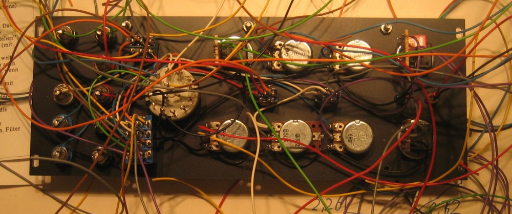
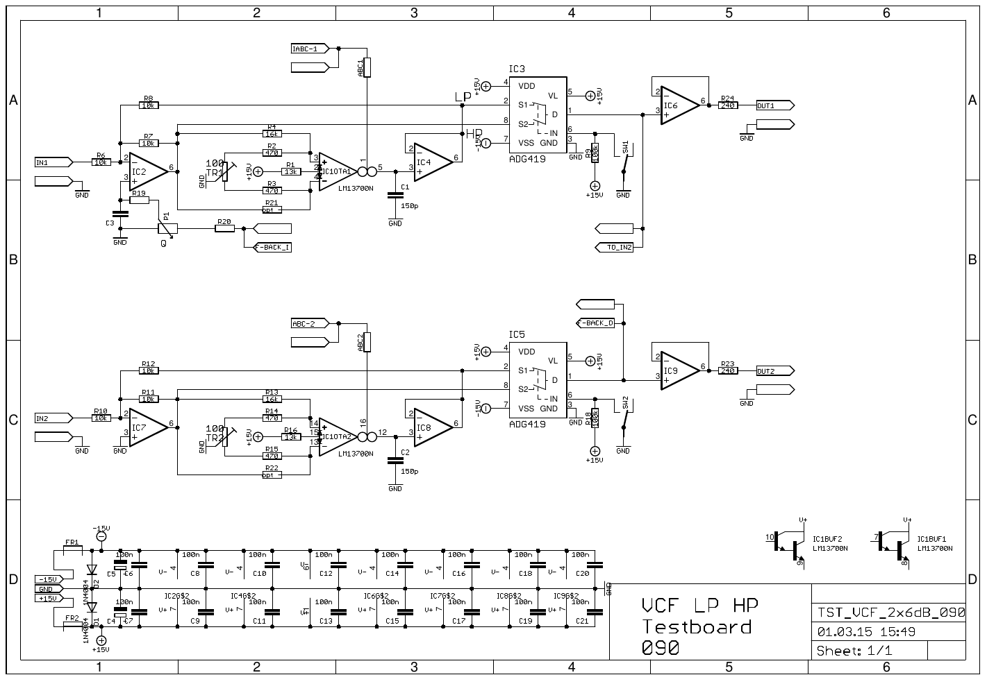
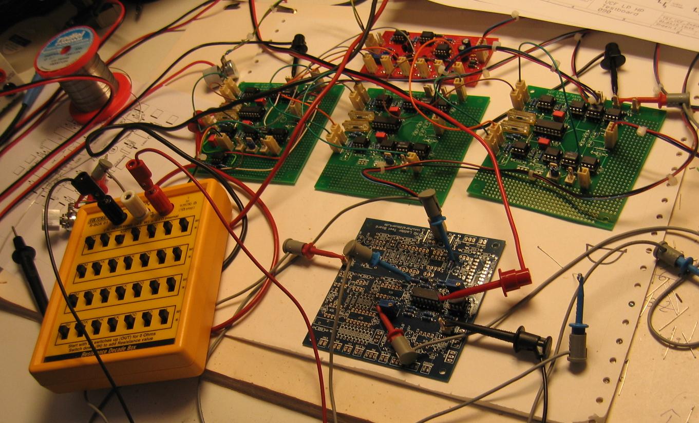
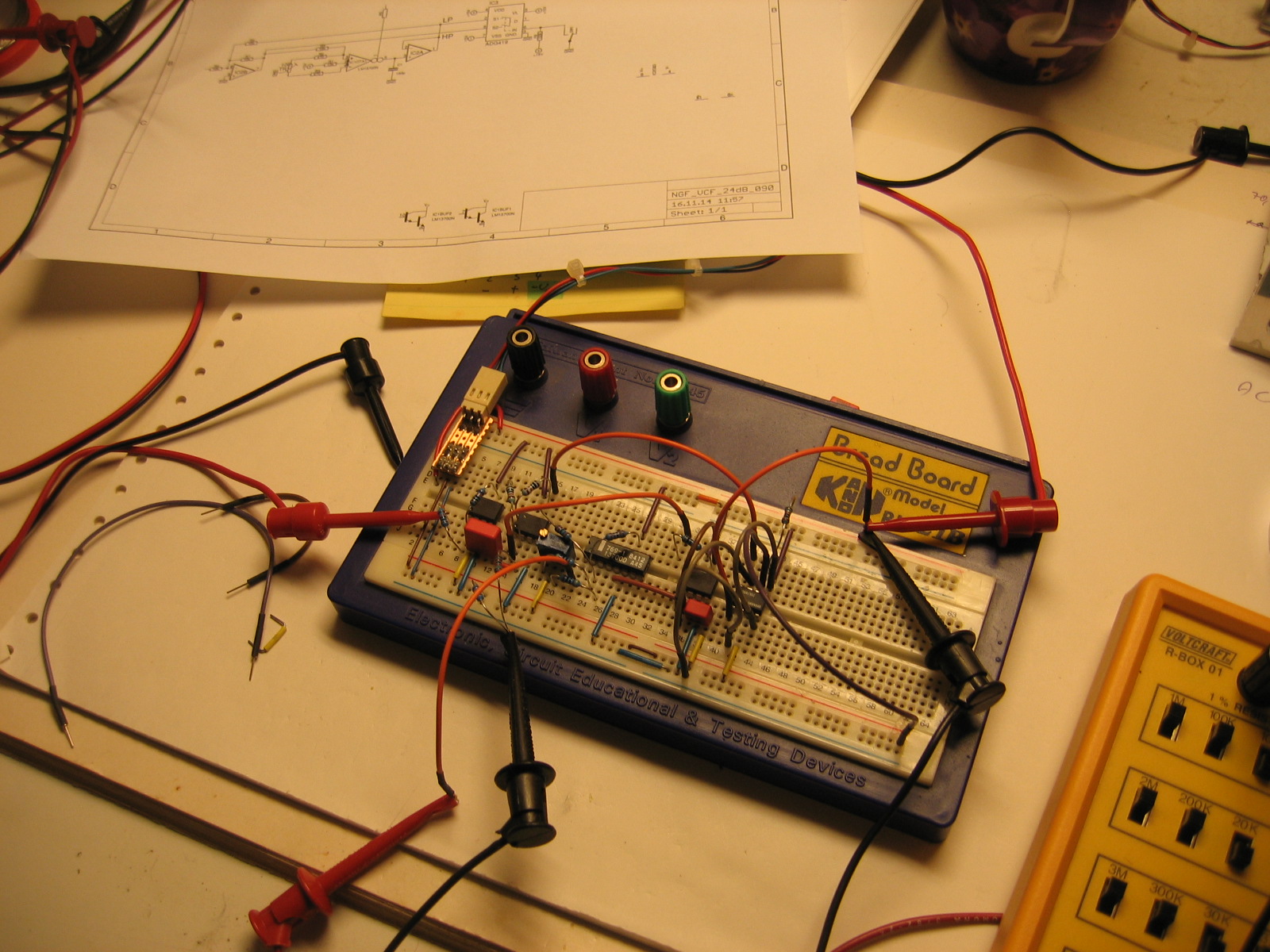
Here is a detail of my Moog Ladder Filter implementation. The Moog Ladder Filter suffers from gain loss when the emphasis / feedback is turned up, as many other filters do. Here is my take on correcting this. With this method the gain loss can be compensated to 100% (or more) if wanted. I made the feedback voltage controllable. So I have already a control voltage proportional to the feedback. This voltage can be used to control a second OTA in the output stage of the filter. The output of the OTA is then added to the regular filter output. No feedback CV means no additional output. Increasing the feedback CV causes the OTA to add to the regular output. The amount is determined by the load resistor (R18 on the schematic) of the OTA. You can adjust it to your needs. It is possible to use a potentiometer here as well.
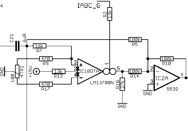
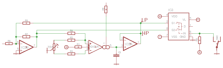
Moog Ladder Filter. Gain loss correction. Schematic detail.
Here are some screenshots from the output with different amounts of gain correction starting with 0% up to 100%
Moog Ladder Filter, output with no gain loss correction. As you can see, the output (blue line) drops significantly.
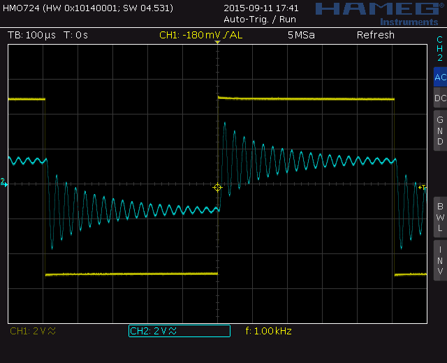
Moog Ladder Filter, no gain loss correction
Moog Ladder Filter, output with gain loss correction. R18 30k:
From here on the peek of the output signal is above the input signal. Watch the headroom of your system!
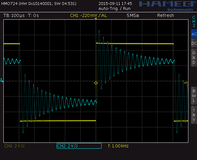
Moog Ladder Filter with gain loss correction R18=30k
Moog Ladder Filter, output with gain loss correction. R18 50k:
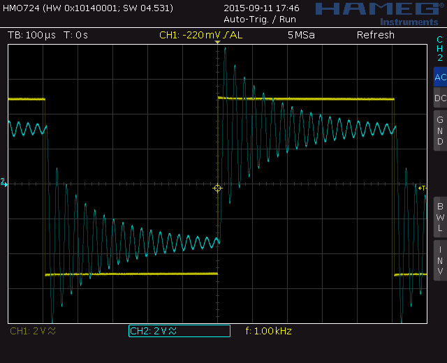
Moog Ladder Filter with gain loss correction R18=50k
Moog Ladder Filter, output with gain loss correction. R18 100k:
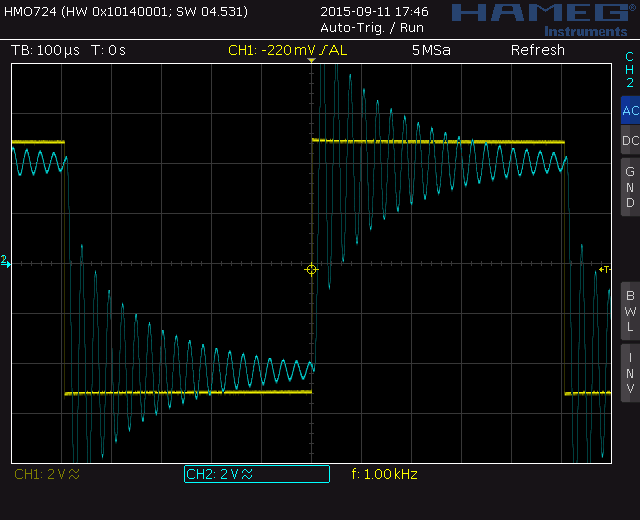
Moog Ladder Filter with gain loss correction R18=100k
Moog Ladder Filter, output with gain loss correction. R18 200k:
As you can see the gain loss is completely corrected here. If you look at the last picture you can see that the peeks of the signals are about 10V. If you use 100% gain loss correction you should have a look at the headroom of your system.
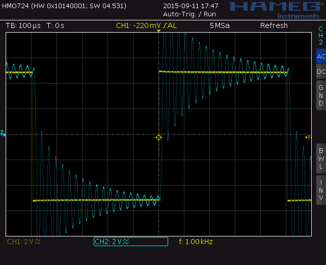
Moog Ladder Filter with gain loss correction R18=200k, Scale 2V
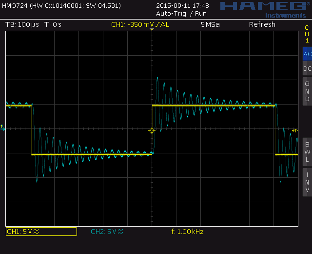
Moog Ladder Filter with gain loss correction R18=200k, Scale 5V