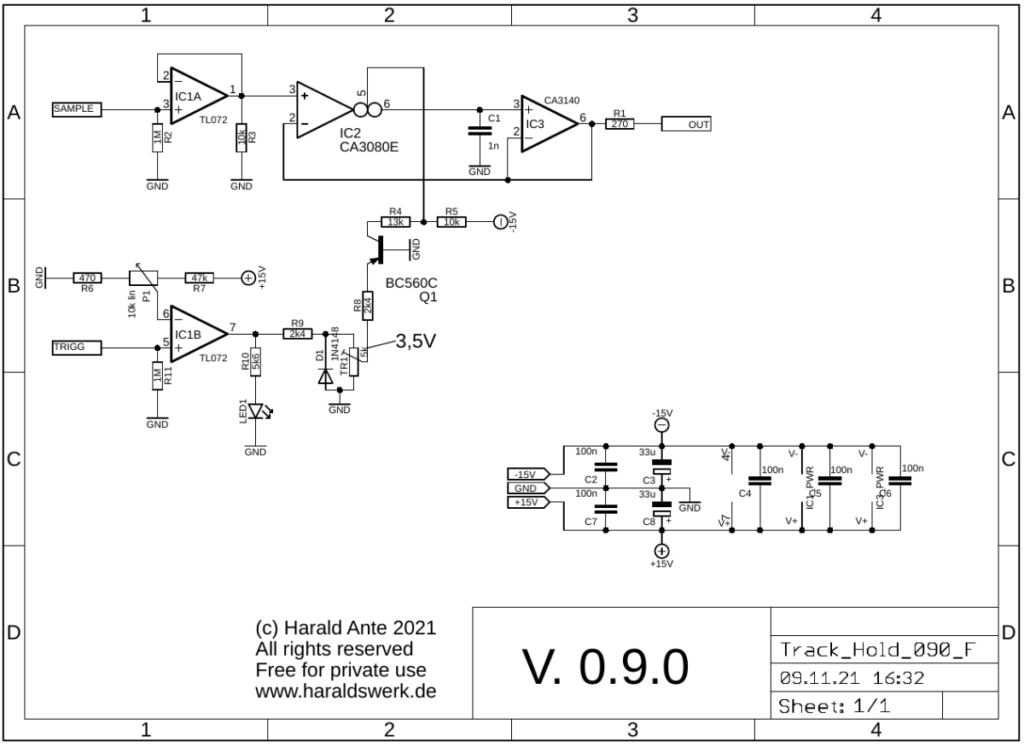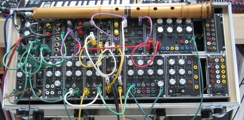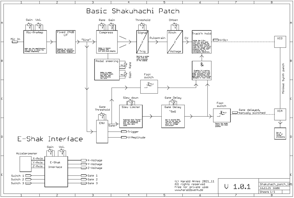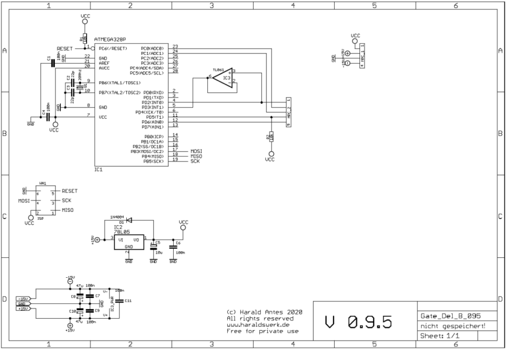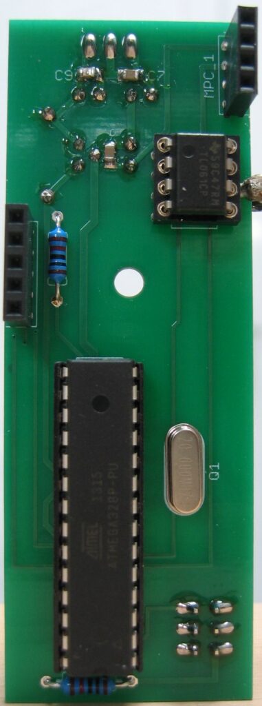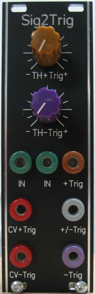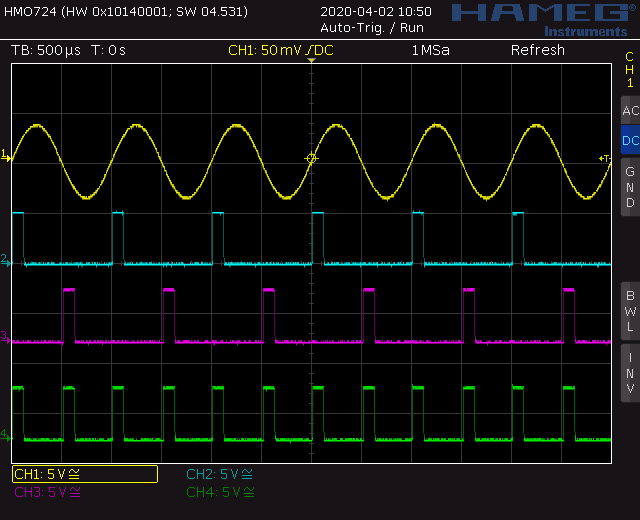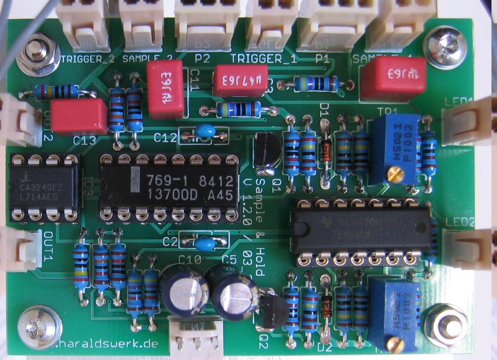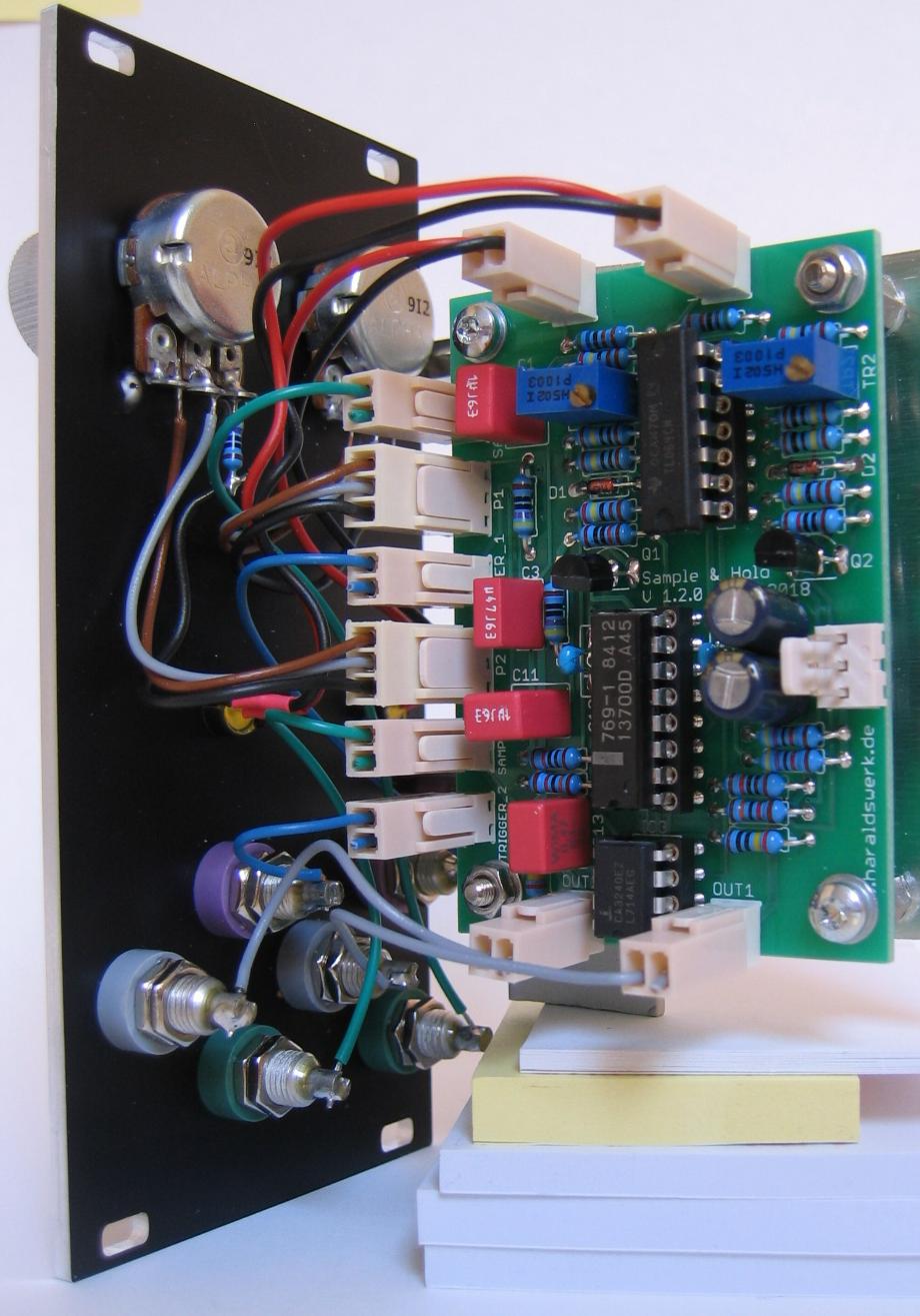
One more module for my Shakuhachi to Synths project. Not exclusively of course. This is a Track and Hold. Which is quite useful for other patches as well. In the Shakuhachi patch it is used to suppress an incomplete pitch to voltage conversion from the Pitch to voltage converter when the player stops blowing. The module tracks the incoming (control) voltage as long as the gate input is high. When the gate goes low the output voltage is kept. The module is DC coupled to track slowly moving voltages. For this one I have used some obsolete parts, which I had laying around. So, if you want to build it, make sure that you can get those parts. You can use it as Sample and Hold as well. Instead of a gate apply a trigger at the gate input.
Specs and features
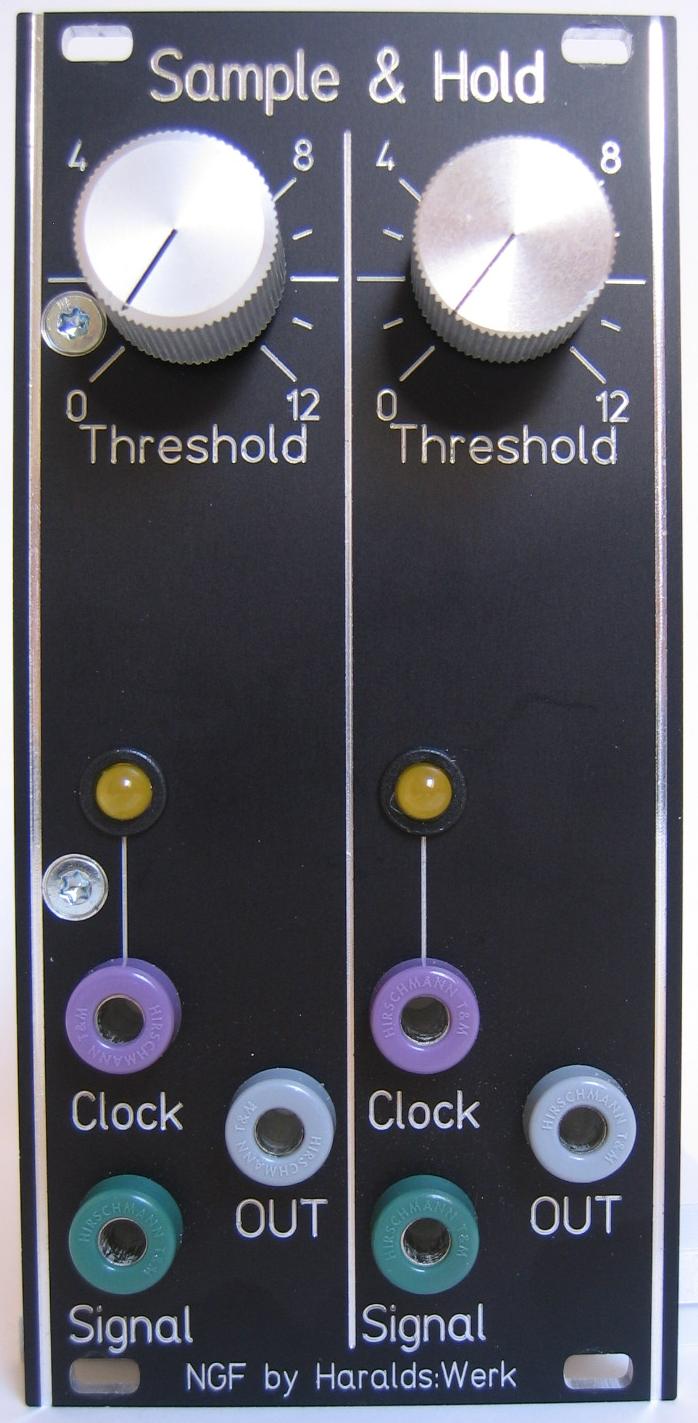
- Track or Sample and Hold
- DC coupled
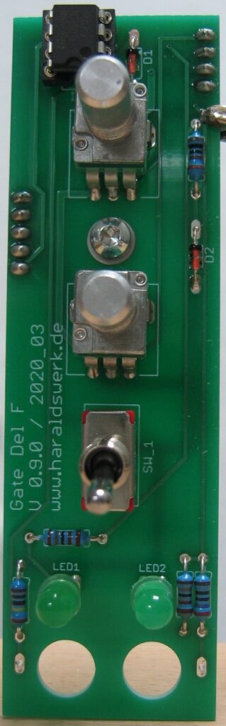
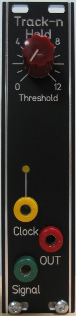
- Gate input with LED
- Signal input
- Signal output
- Threshold
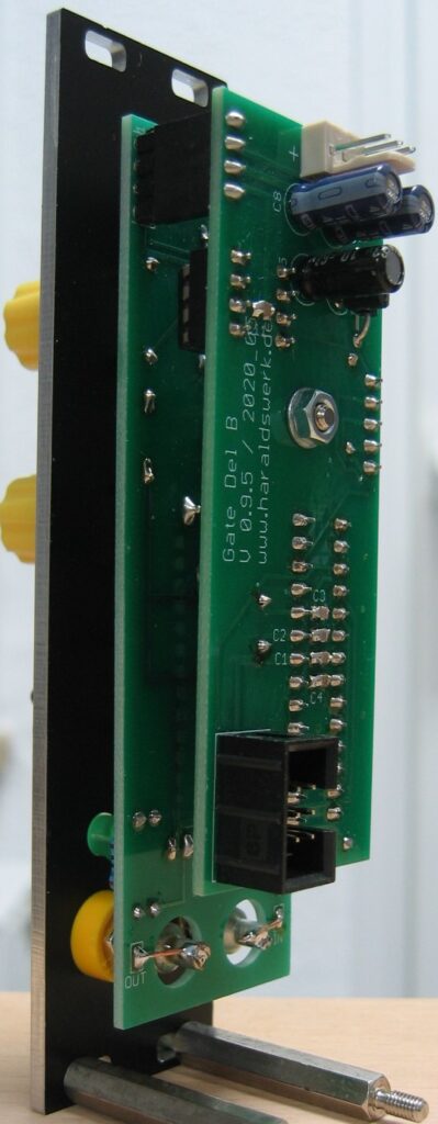
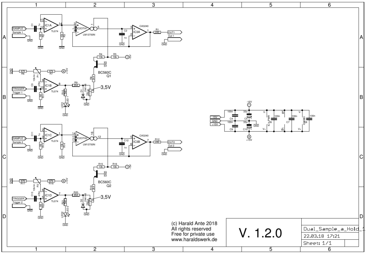
- Runs on +/-12V and +/-15V
- Power consumption below 20mA each rail
The documentation and the Gerber files for download can be found in my website.