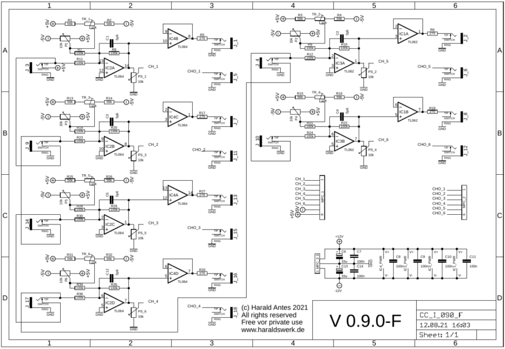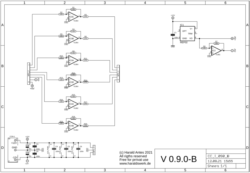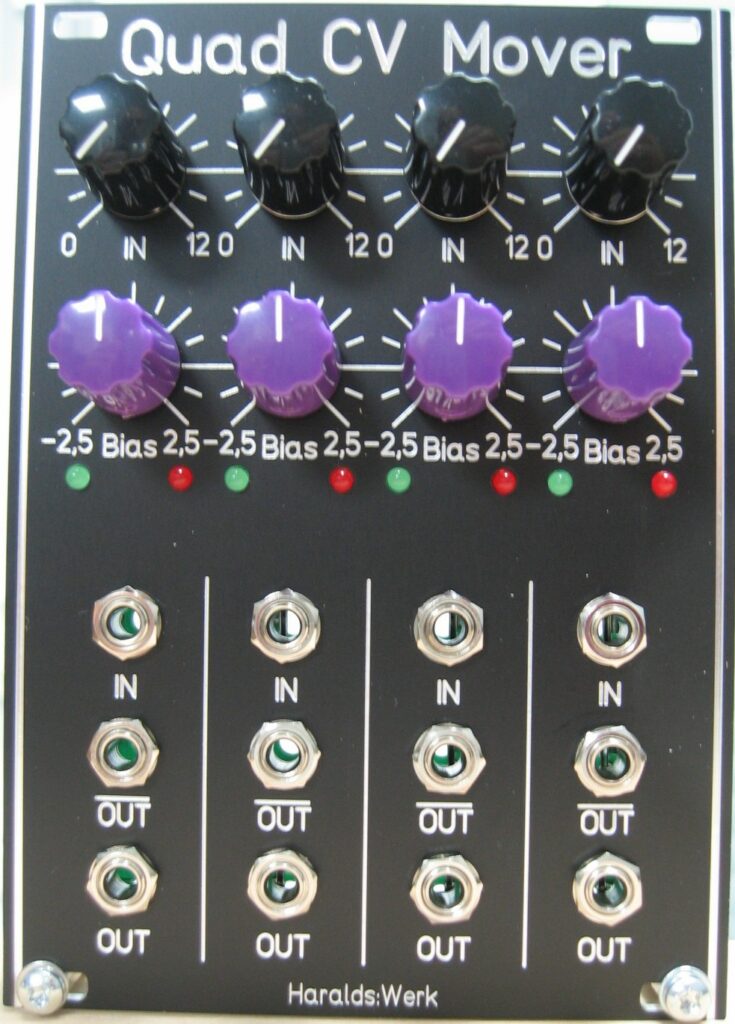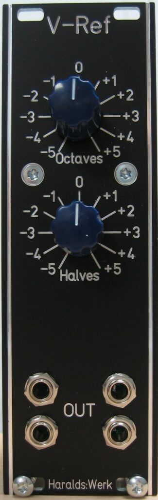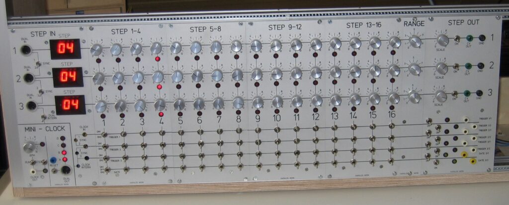
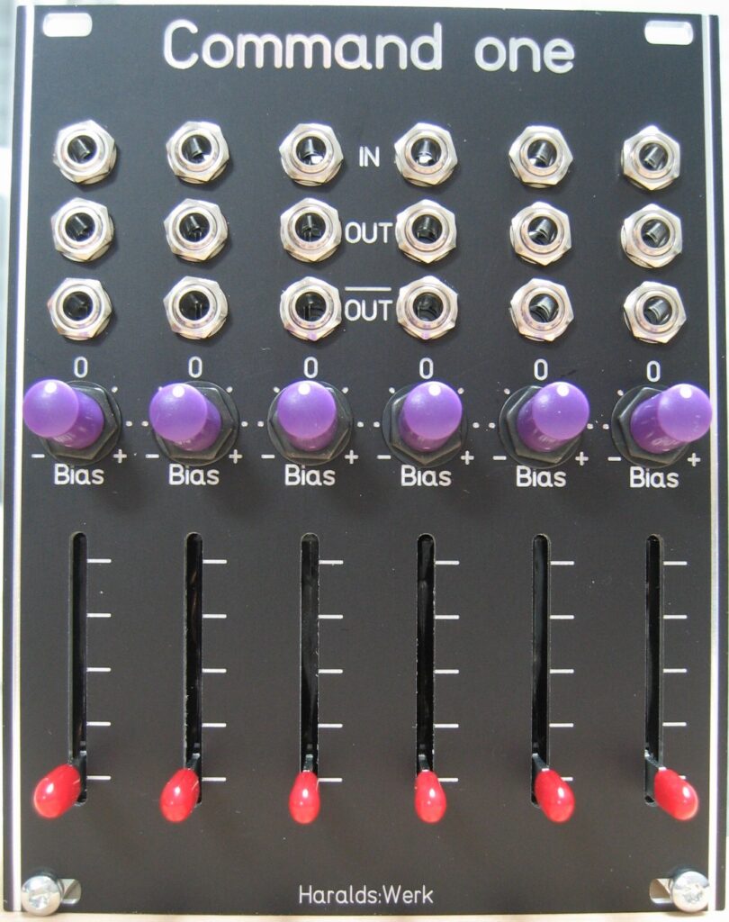
This utility module gives you a wide range of variable and adjustable control voltages from -10V to +10V. This only depends on the knob and slider setting and patching within itself. If used with external input it can attenuate and offset the incoming signal. I use this module for steering modules which lacks of attenuator at the inputs or in greater patches for applying control voltages to far away modules. It is quite comfortable to have the controls in the first row of your case and not somewhere in the messy patch hardly in reach for your hands
Specs and features
- Variable and adjustable control voltages from -10V to +10V
- Six independent active attenuator with external signals
- Positive and negative offset for external signals
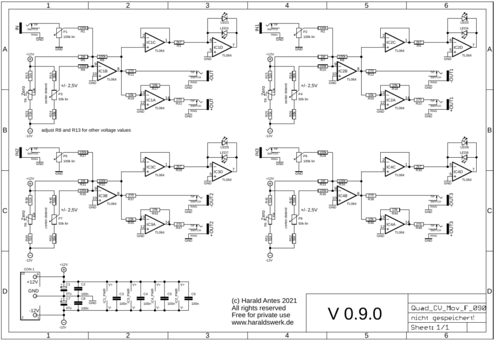
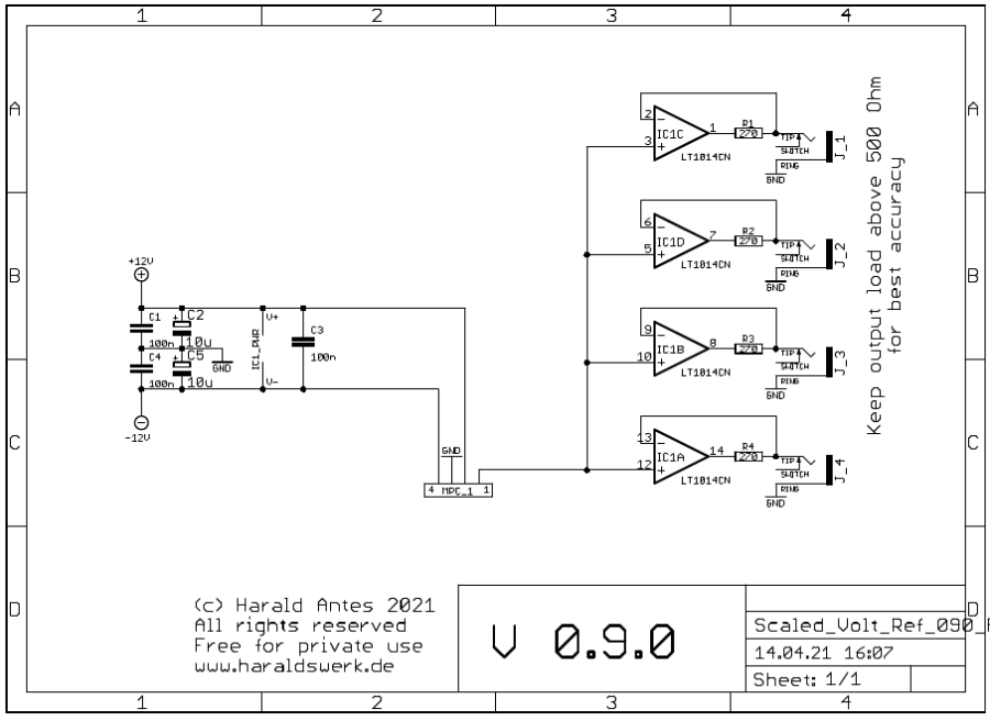
- Runs on +/-12V and +/-15V
- Power consumption below 20mA each rail
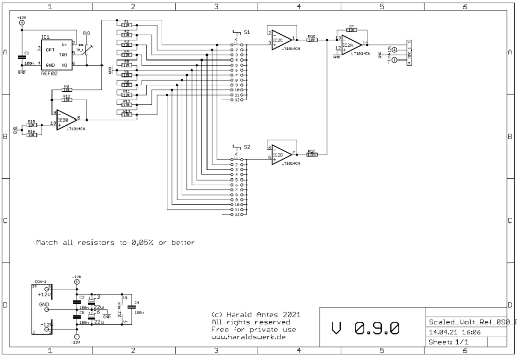
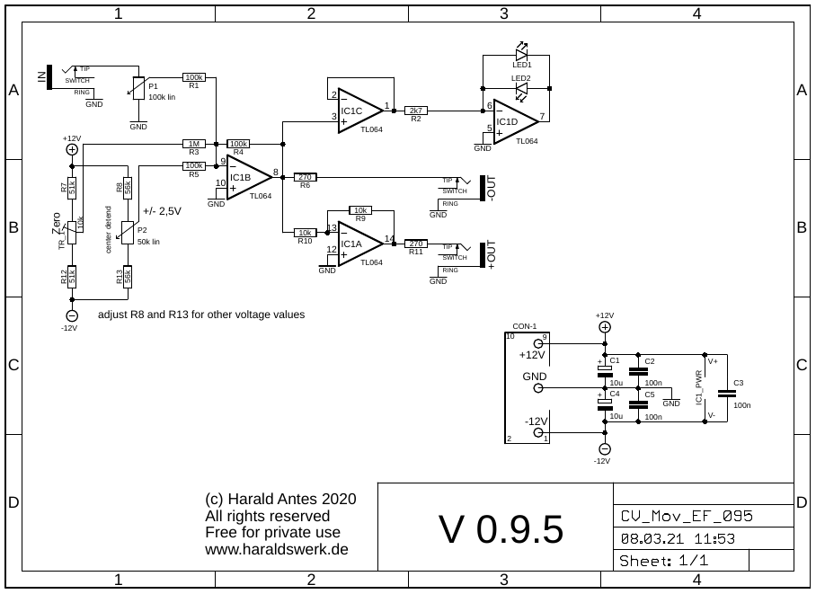
The documentation and the Gerber files for download can be found in my website.