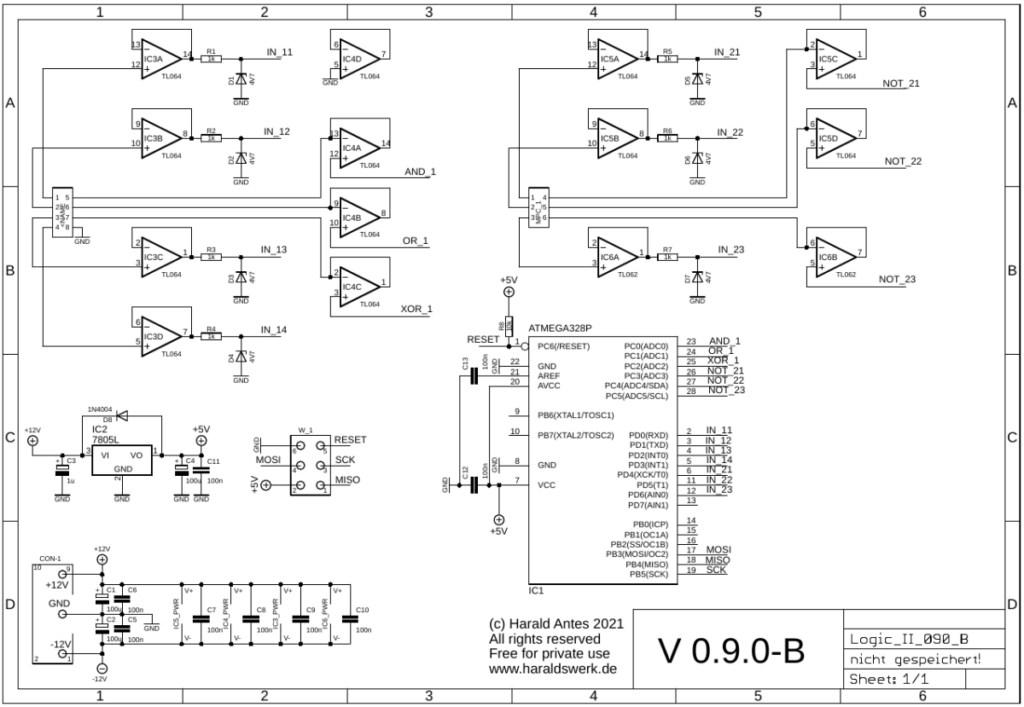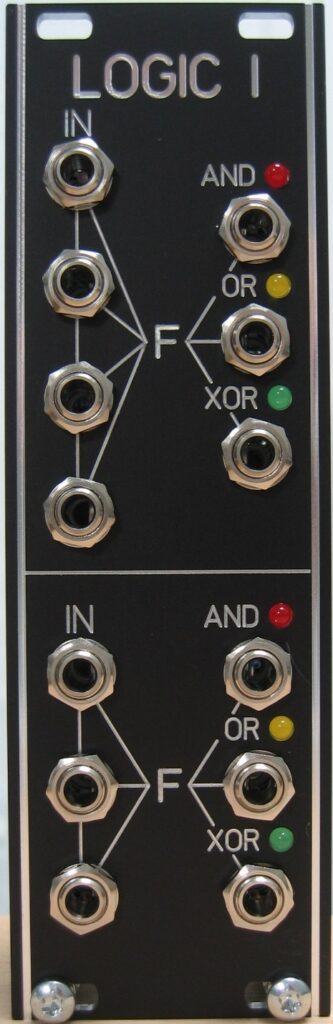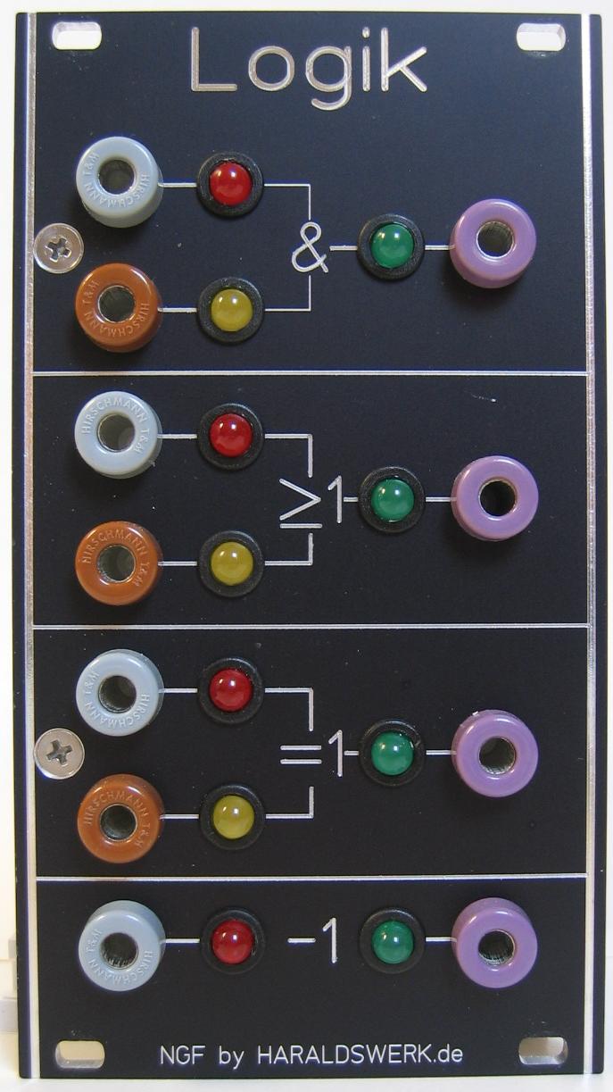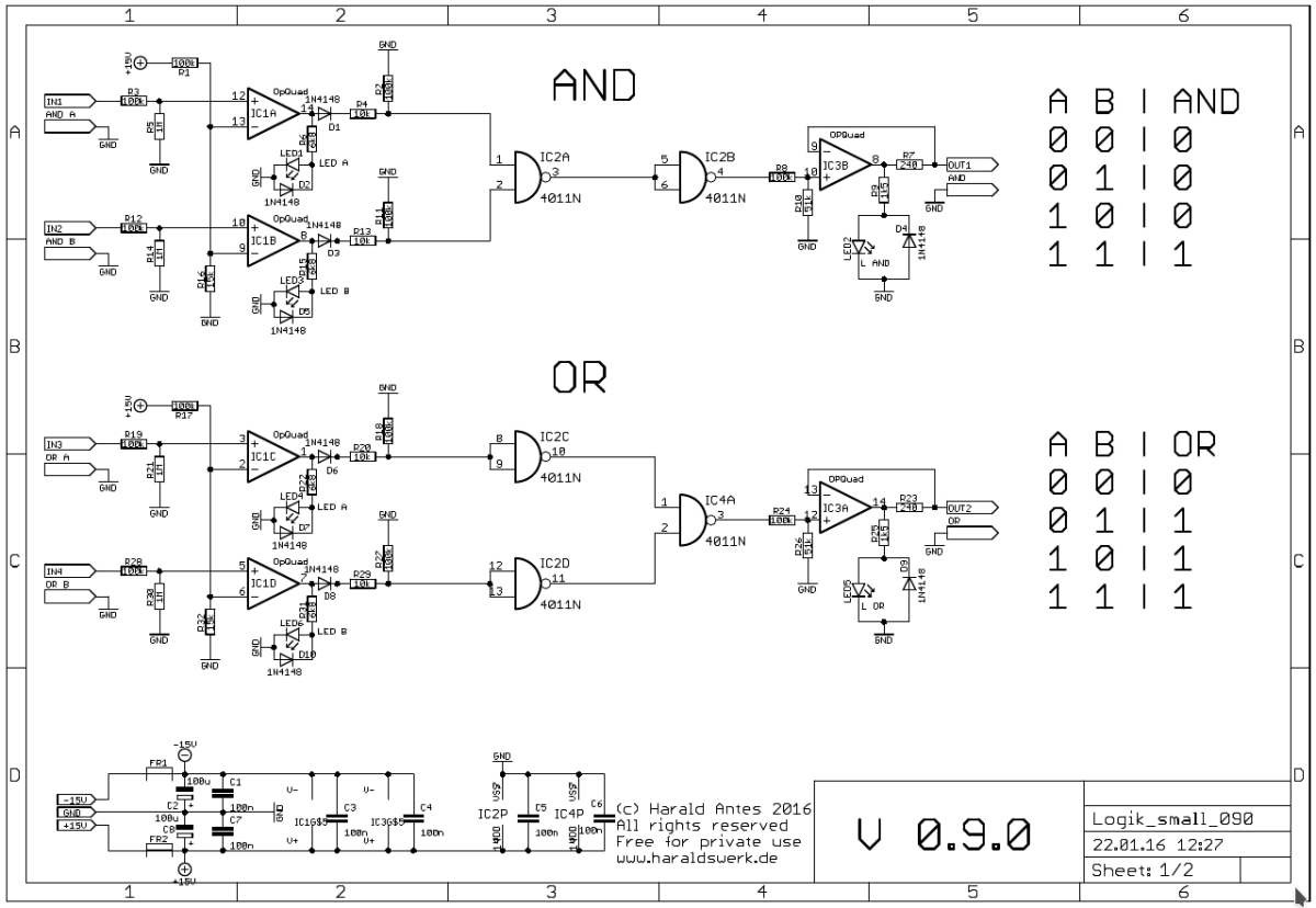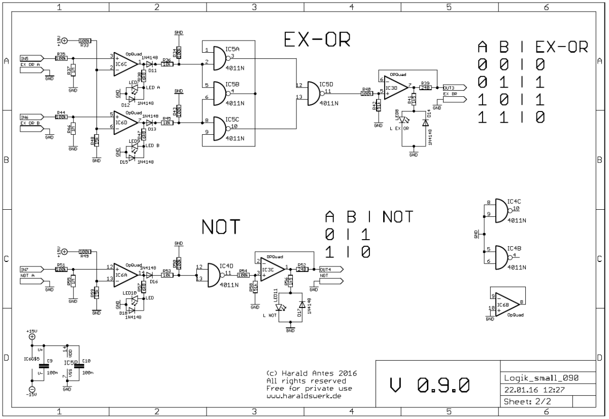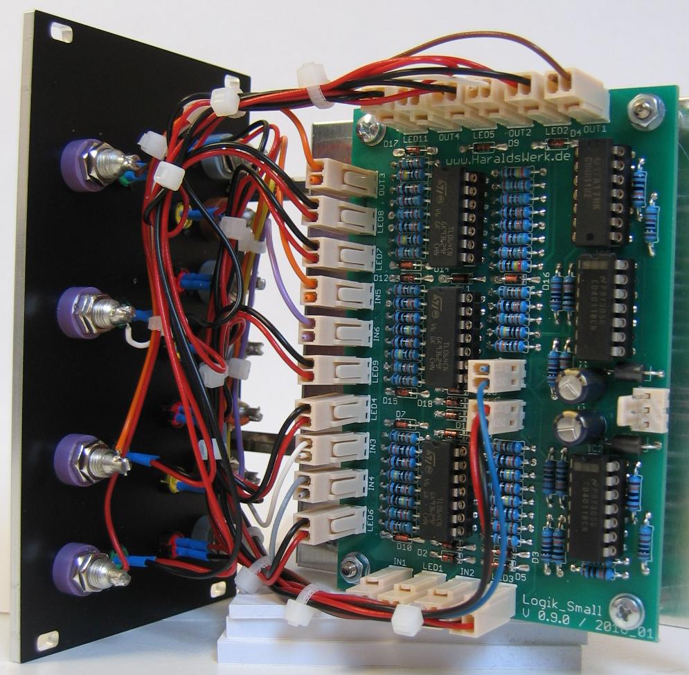
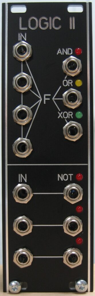
This logic module takes up to four input signals and outputs the logic function AND, OR, XOR dependent on the input signals. The inputs are normalized so you can use less then the four inputs. It has three NOT functions as well.
Specs and features
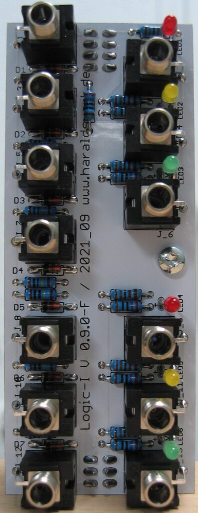
- Up to four input signals
- AND, OR, XOR parallel out
- Three NOT functions
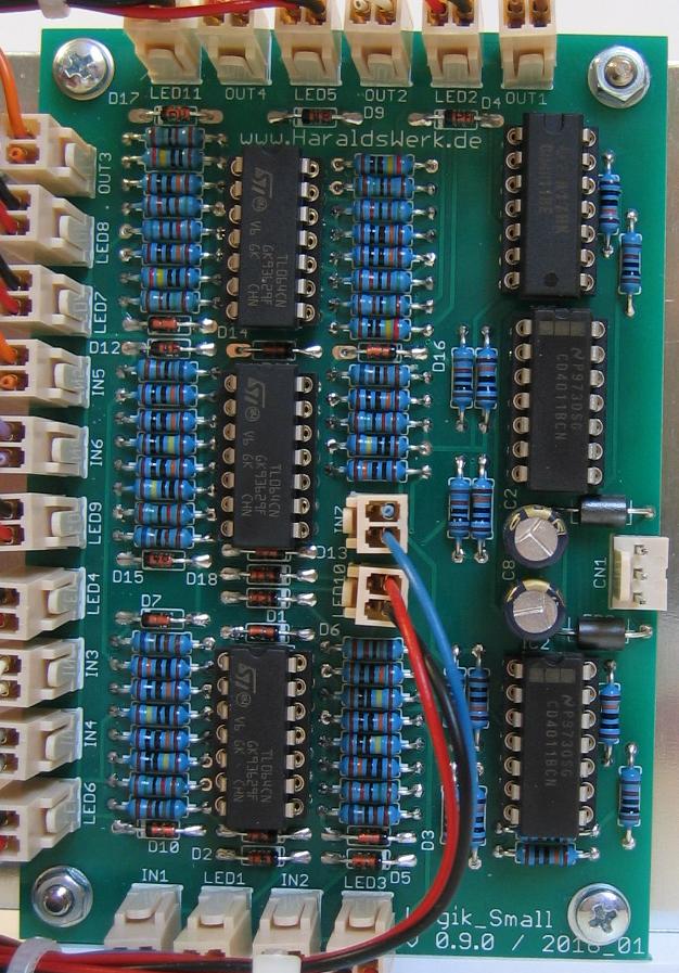
- Runs on +/-12V and +/-15V
- Power consumption below 30mA positive rail. 5mA negative rail.
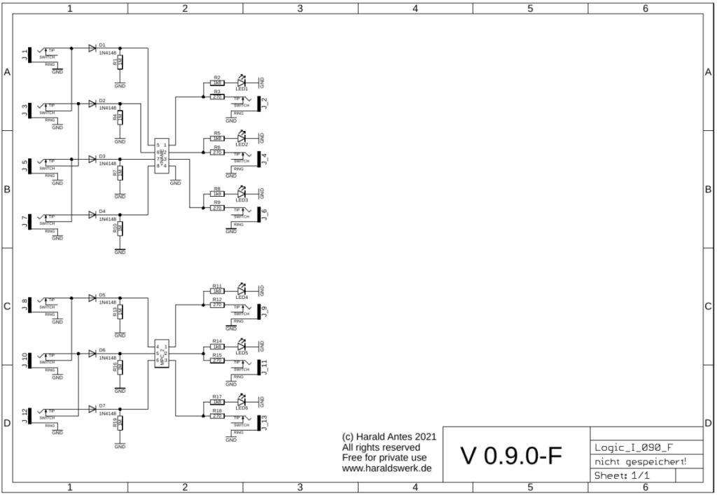
The documentation and the Gerber files for download can be found in my website.