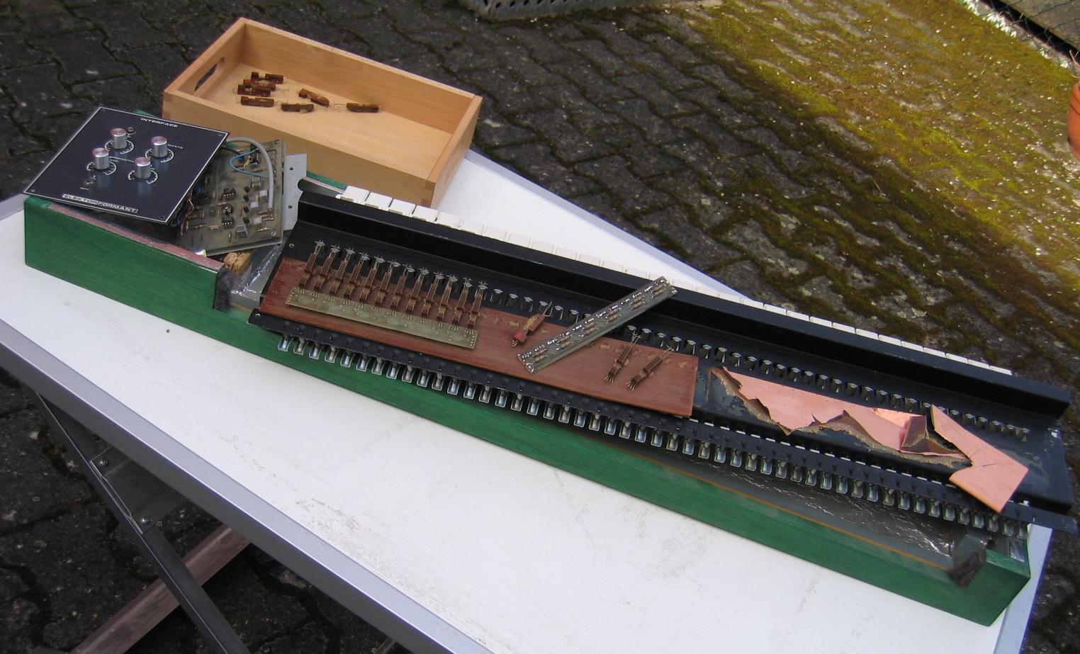
This is the last post about the mechanics. I promise. I have now a mechanical working keyboard with Kimber Allen contacts and the basic wiring. Next step are the electronics. I have them working since 2004 but it might be useful to do some rework with newer parts. I have to move from stripboard to PCB as well.
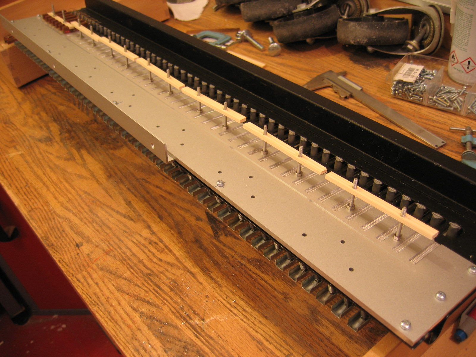
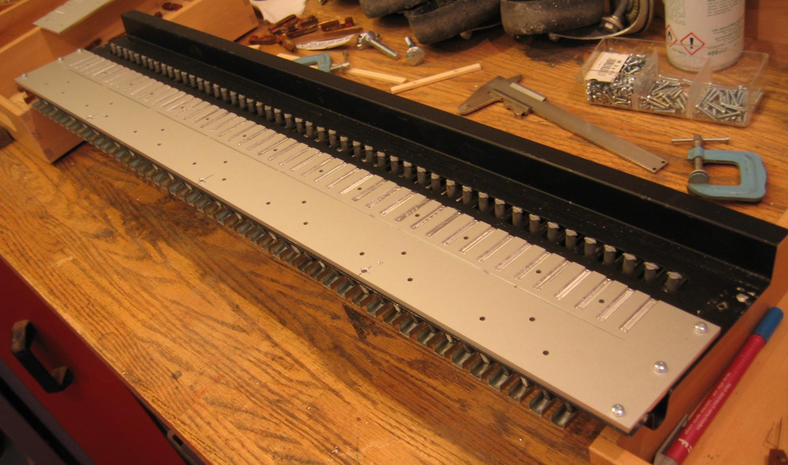
New holder waiting for contacts
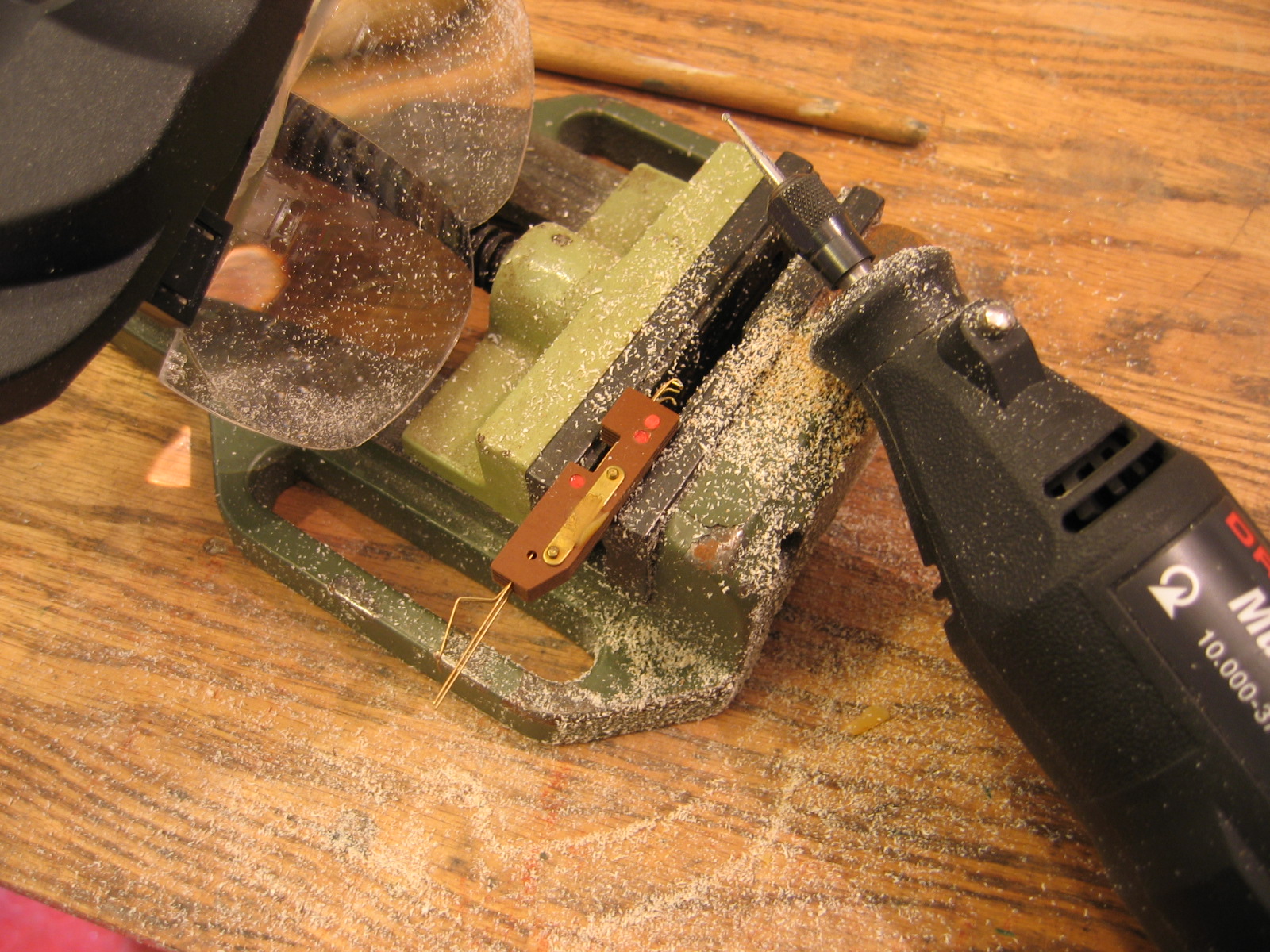
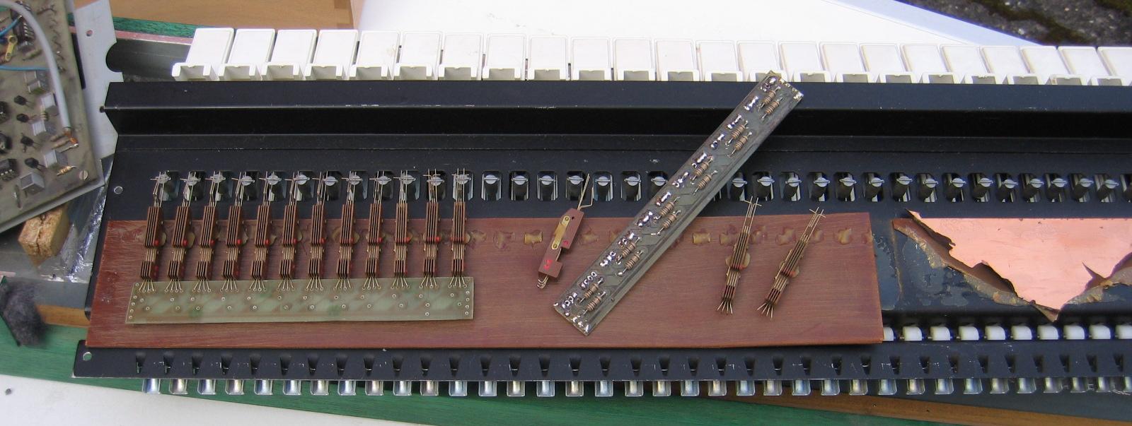
Fitting the contacts and do some rework if needed.
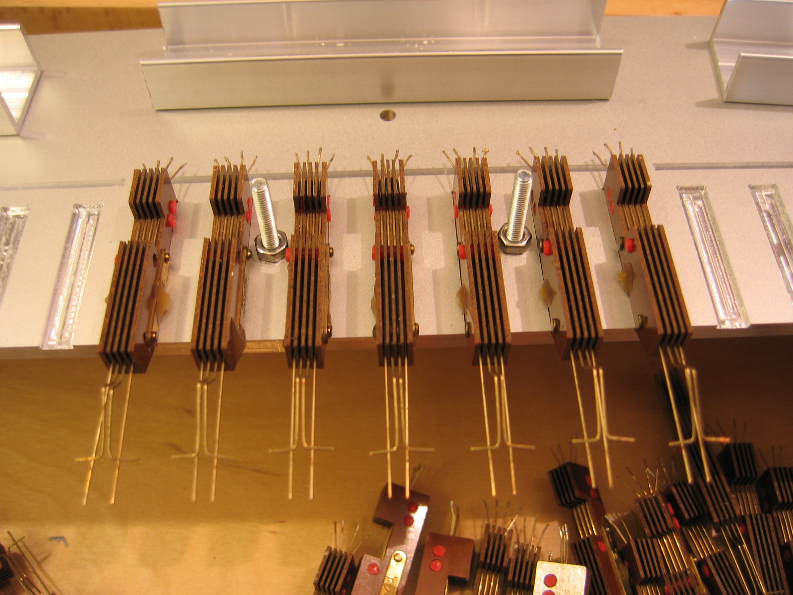
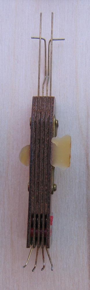
Fitting the Kimber Allen contacts
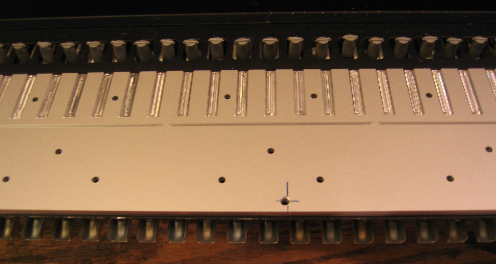
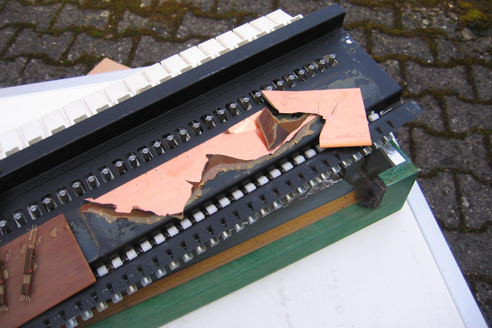
Fitted and mounted with PCB
Fitted and mounted with PCB
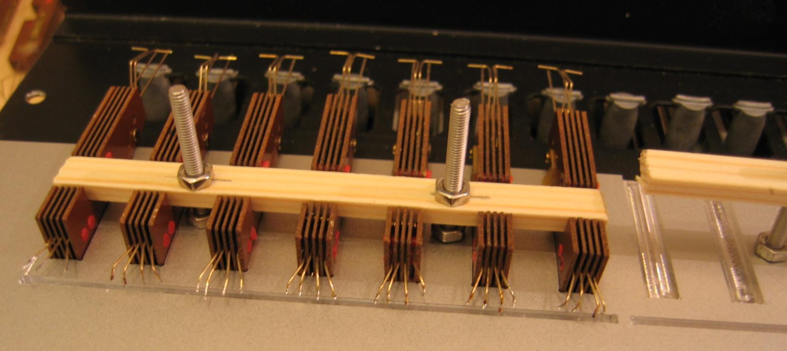
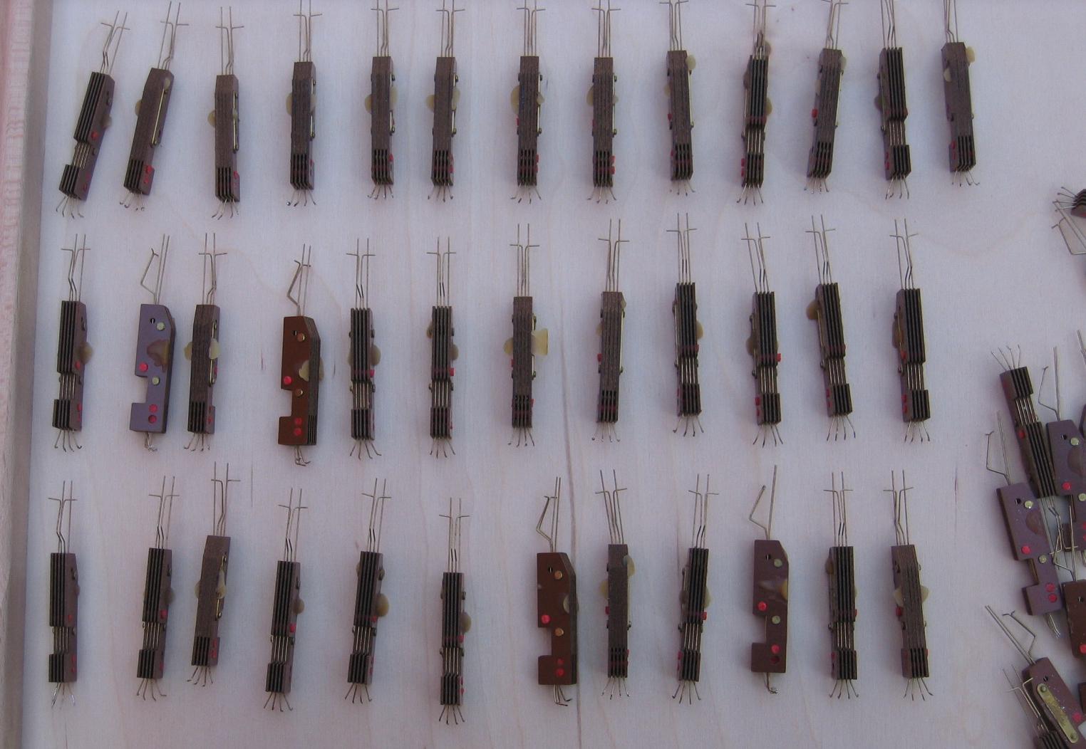
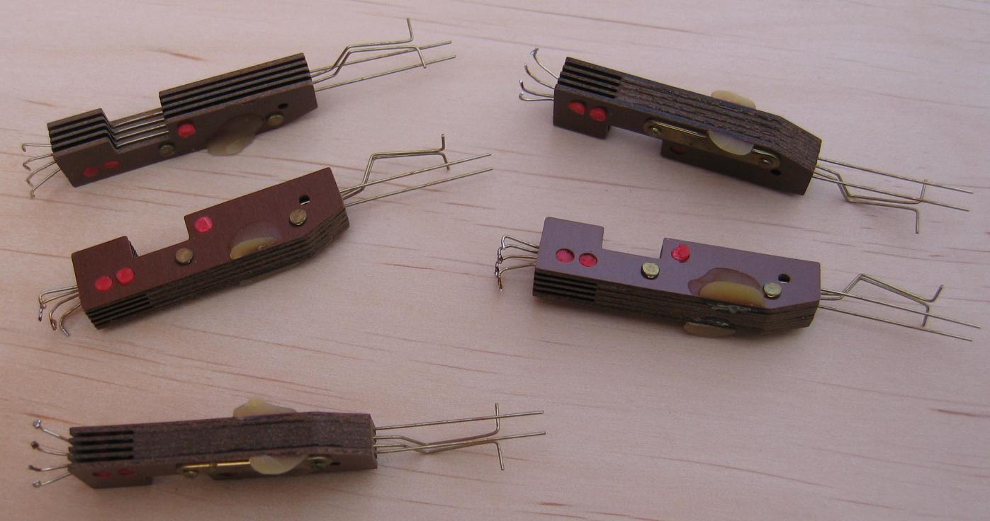
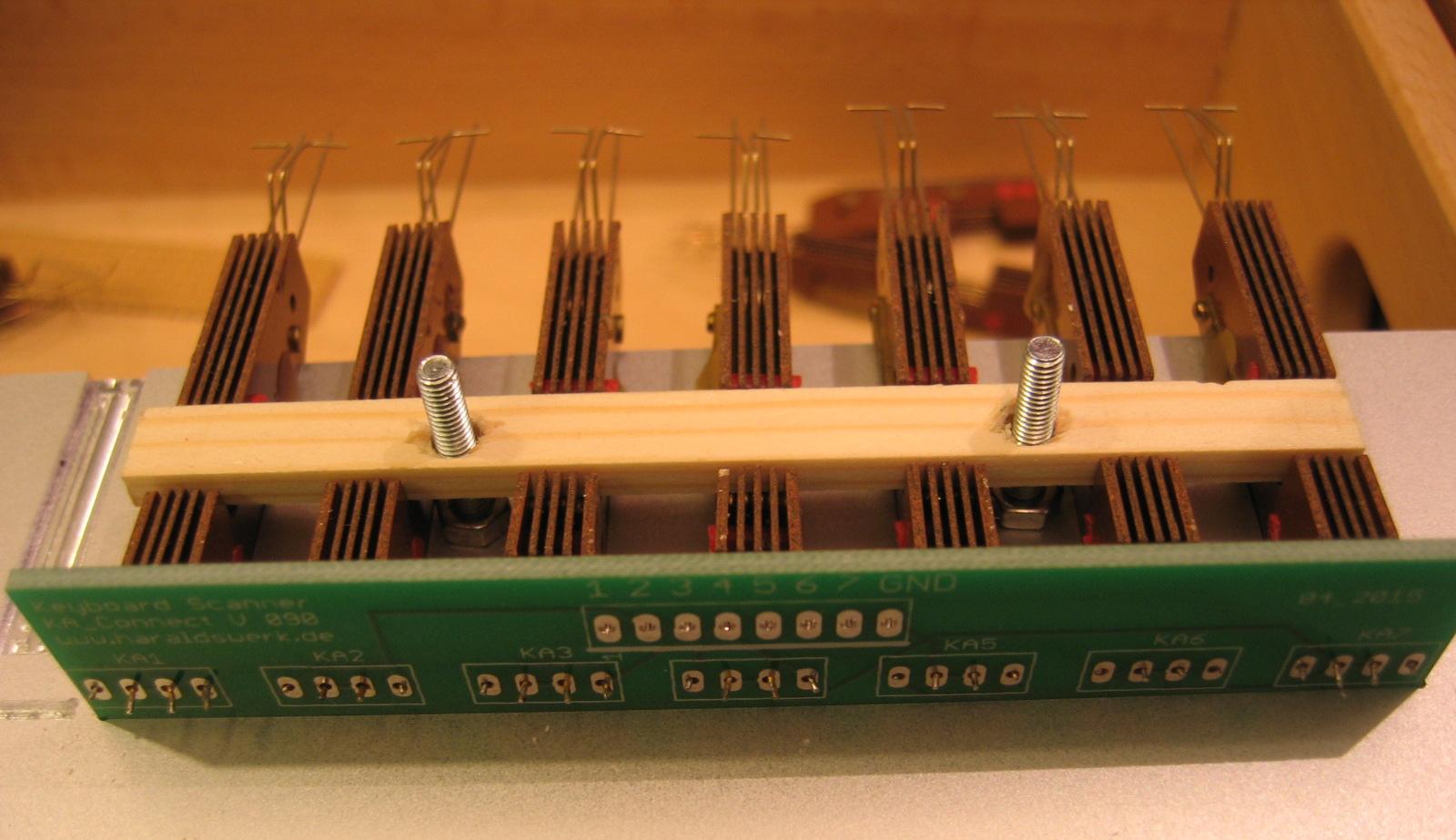
Soldered and screwed
Contacts soldered and screwed
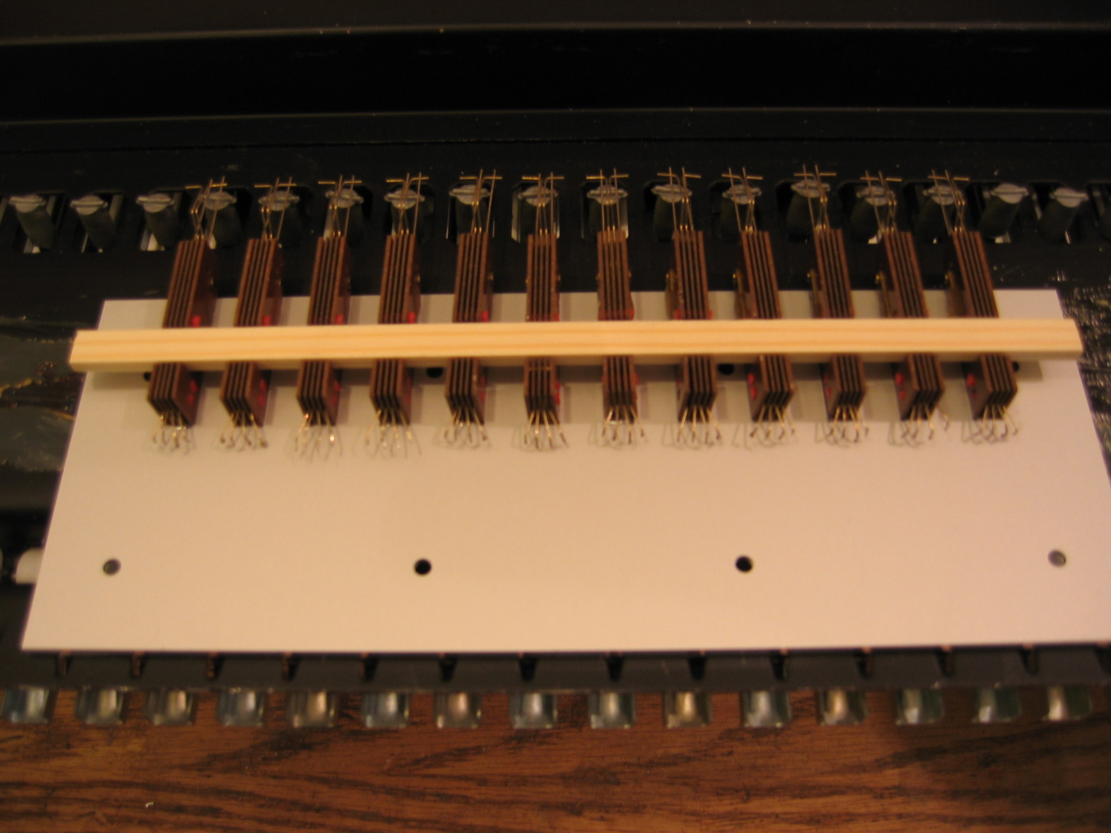
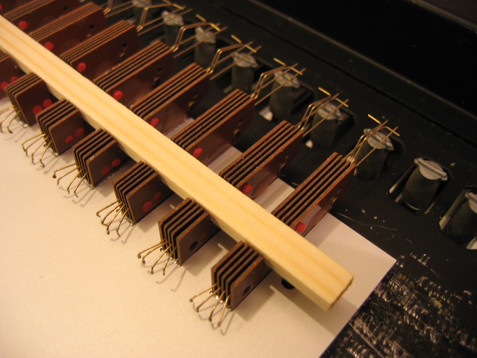
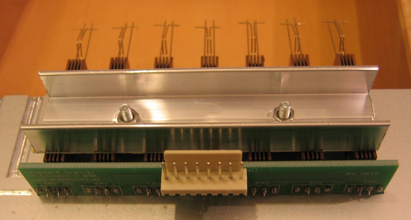
Putting it together
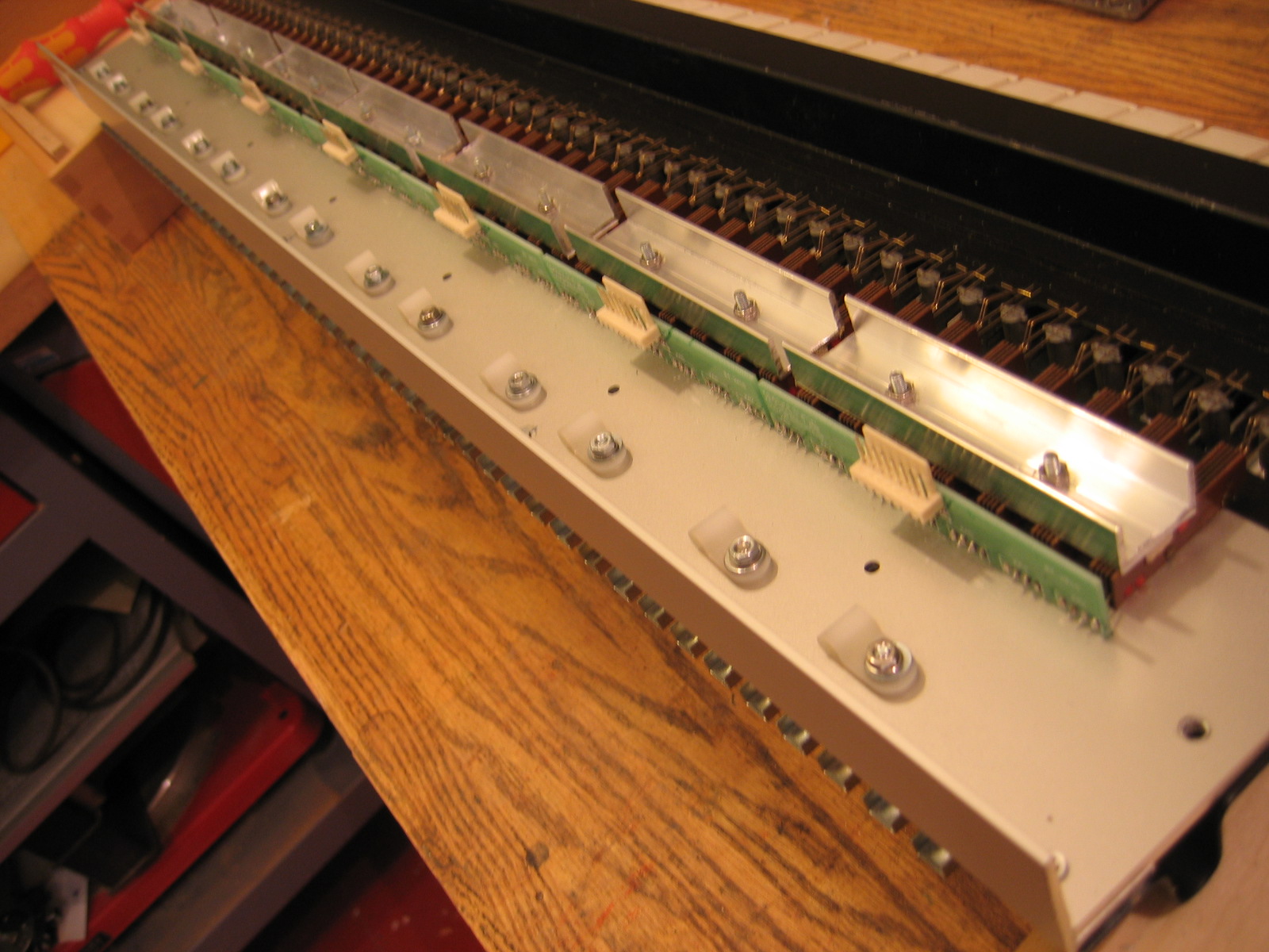
Contacts mounted with keyboard action
Some wires
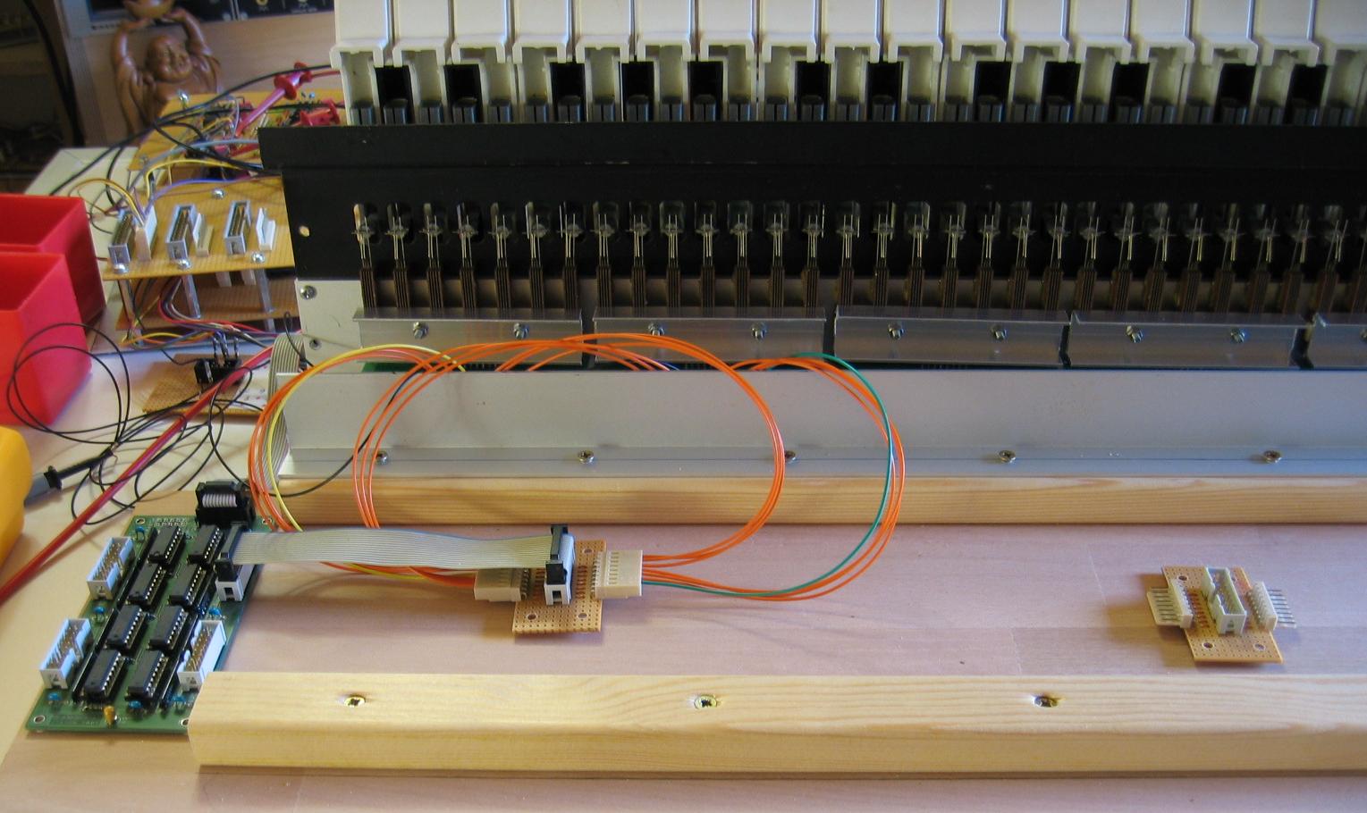
First wiring to the shift register
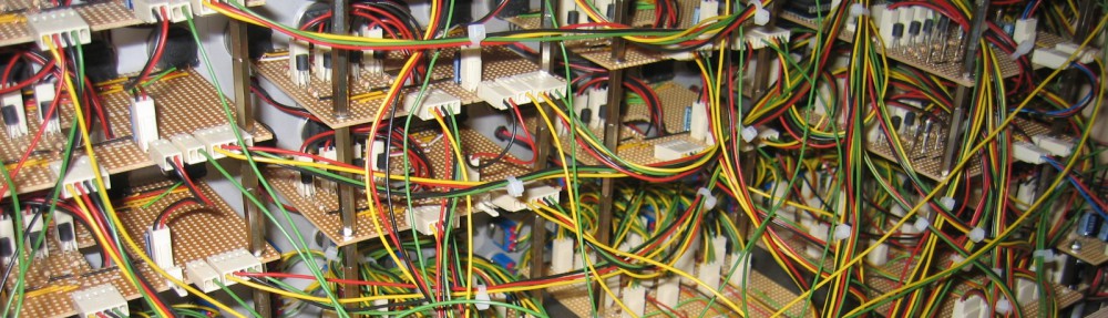
Old scanner electronics from 2004
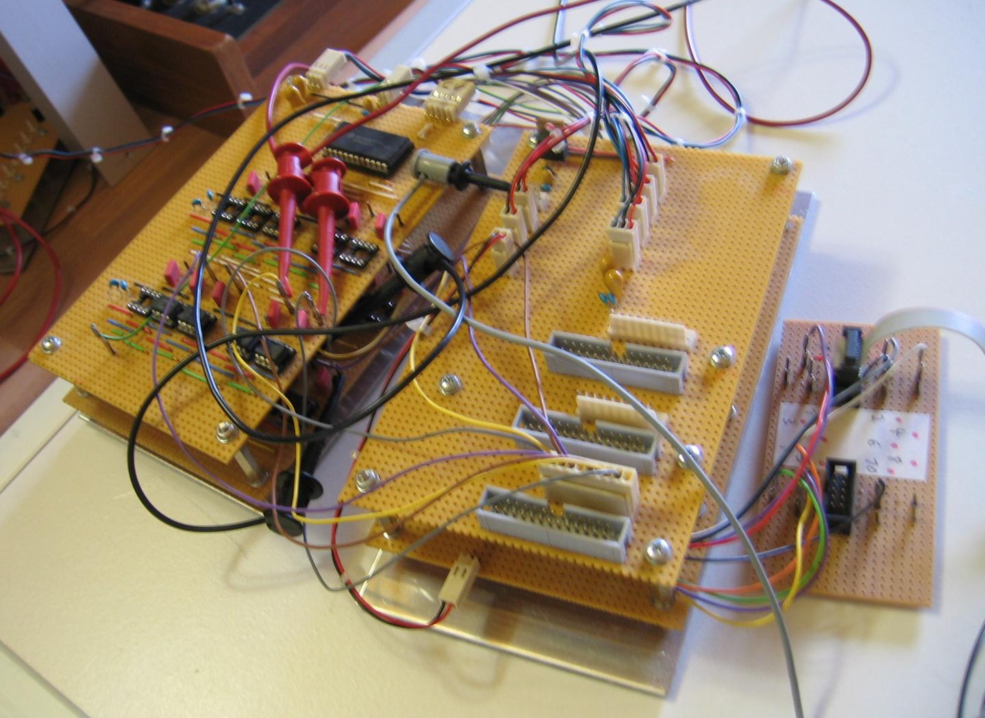
Old scanner electronic
And my first “keyboard” from 2004

First test keyboard
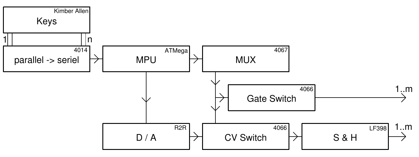
The new keyboard mechanic is working quite well with the old electronic. It is a lot of fun playing chords with the synthesizer. Next step is to think about the electronic. I want to get rid of the old stripboards and make some small PCB. Back then i used a ATmega8 and shift registers for keyboard scanning and a 16bit R2R ladder for DA conversion. Programmed in assembler. Maybe it is time to redo it in C and using a DA chip. I’ll give it a try.