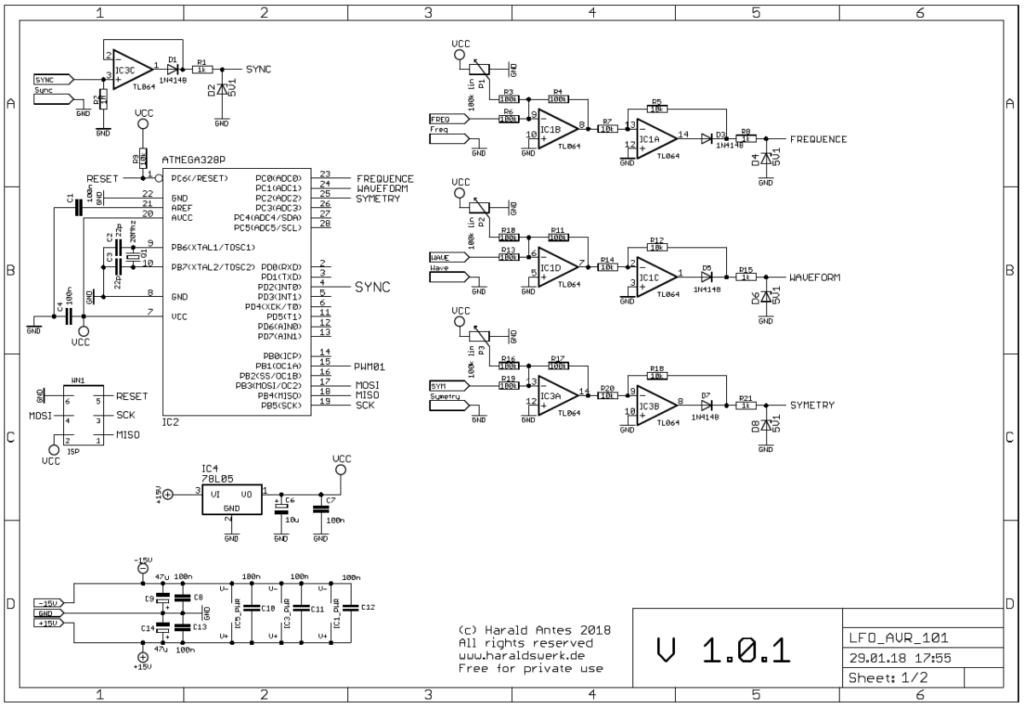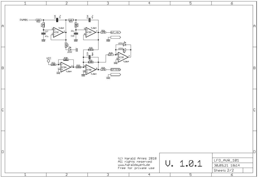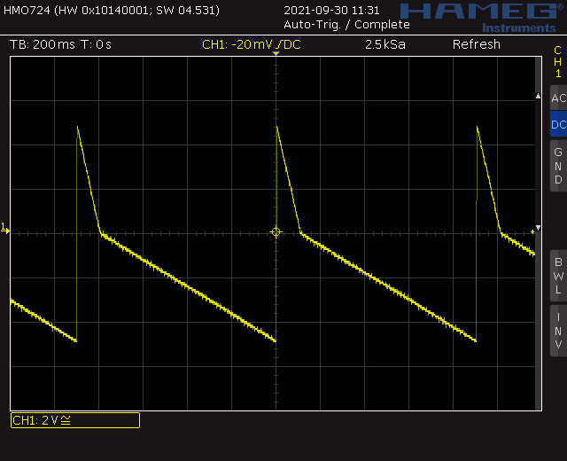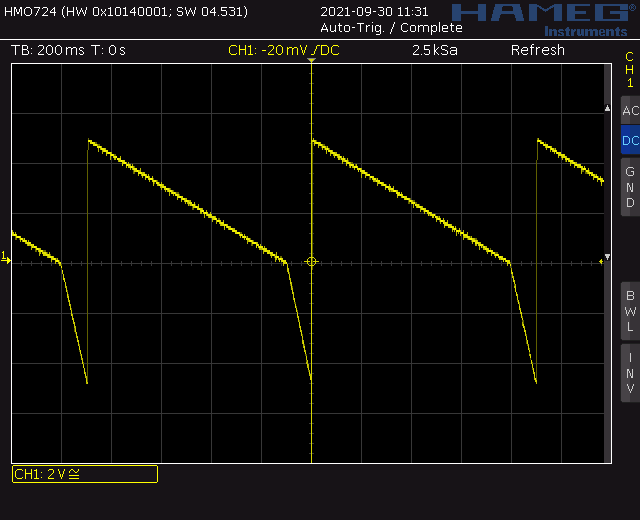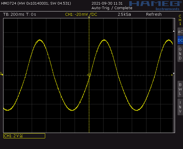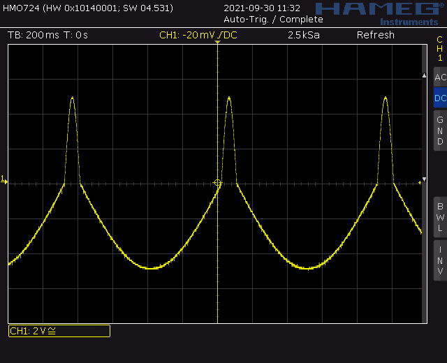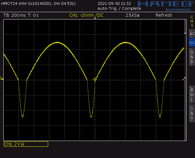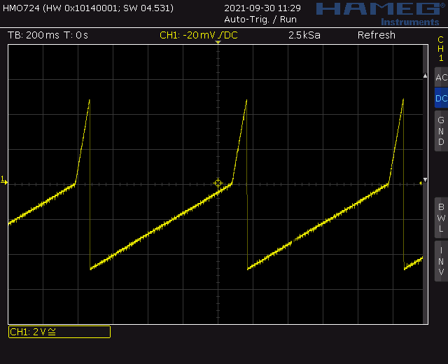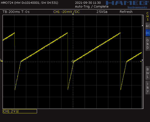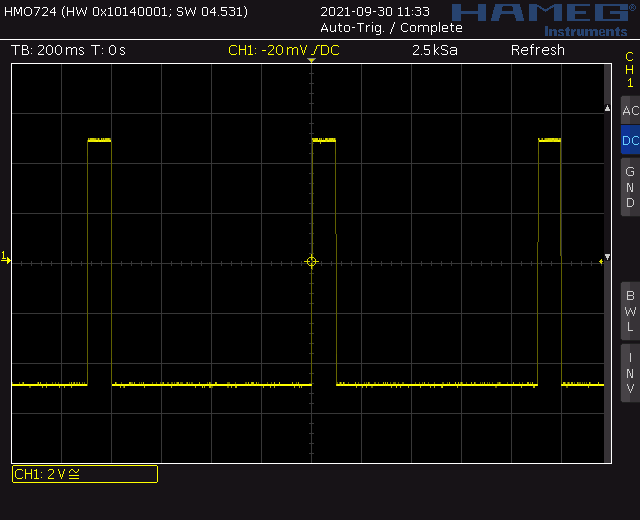
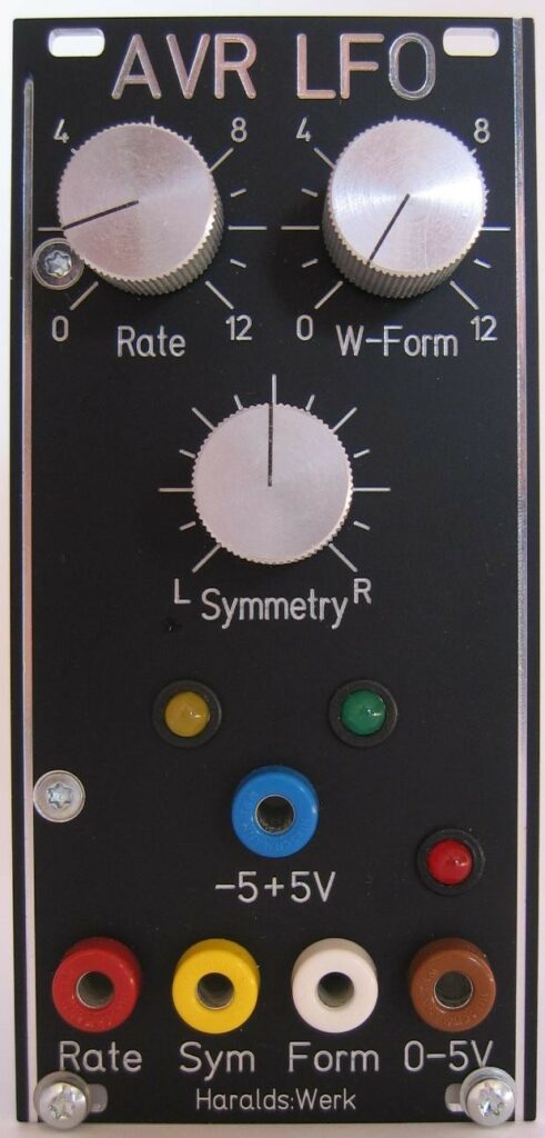
This is an old project dated back to December 2017. It was intended to learn some basics about the hard- and software of the ATMEGA series from AVR. It is kept simple. Just three analog inputs, one interrupt input and PWM output with filter are used. It is up to you what software you want to run on it. Here I made a simple voltage controlled VCO with variable symmetry. Speed, waveform and symmetry are voltage controlled. So you can change the triangle from ramp up to triangle to ramp down. Or make one halve of the sine very small. See screenshots below. This software was mainly written to test the hardware. To my surprise it worked sufficiently well for a LFO. So I leave it as is for the moment. No fancy accumulation with fixed point arithmetic and increment interpolation. Of course there is a lot room for improving the software. I know.
Specs and features
- Voltage control for speed, waveform, symmetry
- Bipolar and unipolar output
- Square, triangle, sine, ramp up, ramp down waveform
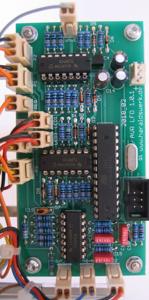
- 20MHz crystal
- 19.5kHz PWM 10bit resolution
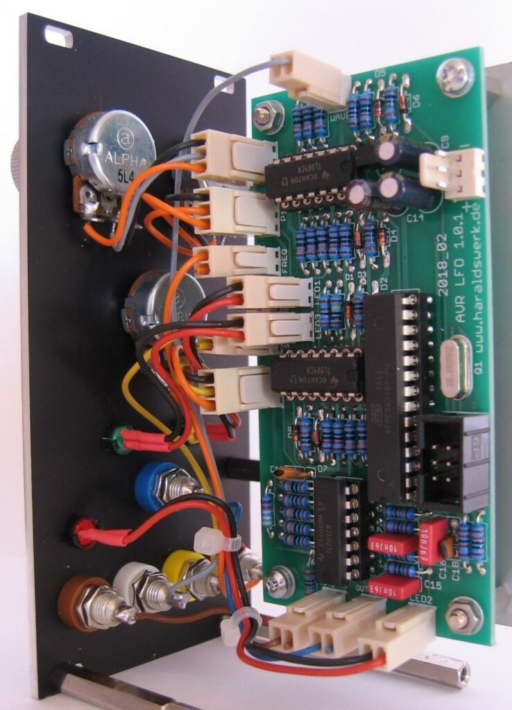
- Runs on +/-15V and +/-12V
- Power consumption around 30mA positive, 5mA negative rail
The documentation and the Gerber files for download can be found in my website.