Logic I

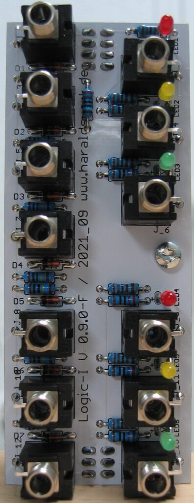
Logic I:Front view

This logic module takes up to four input signals and outputs the logic function AND, OR, XOR dependent on the input signals. The inputs are normalized so you can use less then the four inputs.

Specs and features

  • Up to four input signals
  • AND, OR, XOR parallel out
  • Runs on +/-12V and +/-15V
  • Power consumption below 30mA positive rail. 5mA negative rail.

The documentation and the Gerber files for download can be found in my website.
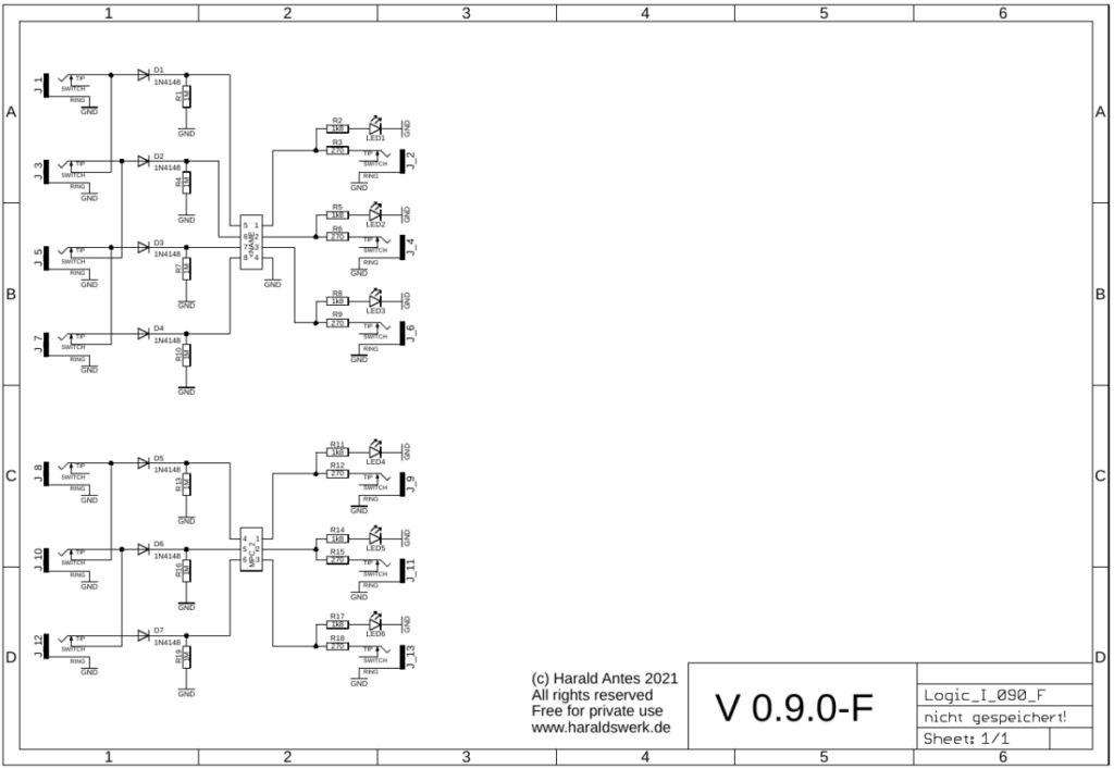
Logic I: Schematic control board
Logic I: Schematic main board

Nothing special to mention. On page one you see the input and outputs. On page two are the input protection circuitry, the microprocessor and the output buffers. The logic is done in software.

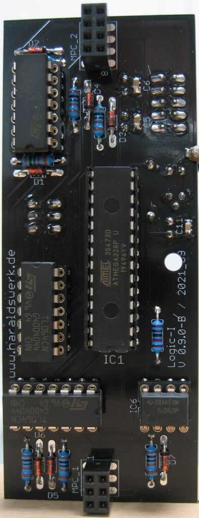
Logic I: Populated control board
Logic I: Populated main board
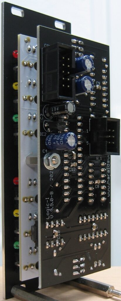
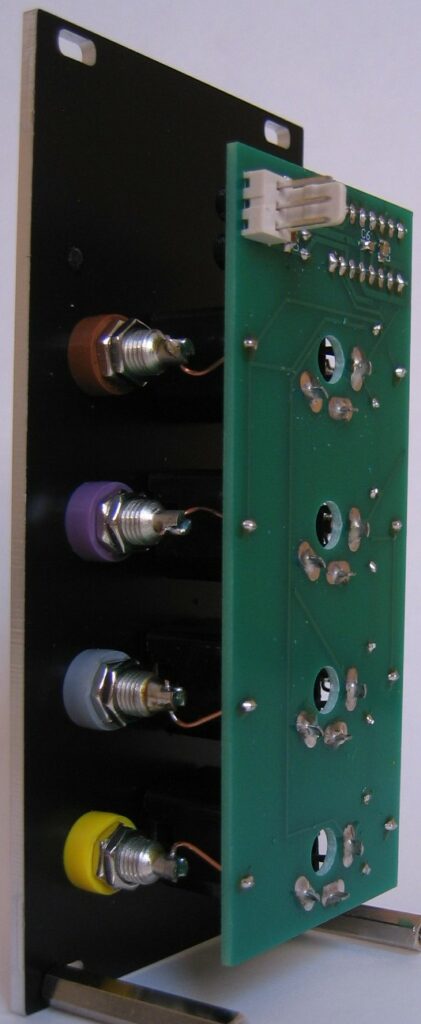
Logic I: Back view
Logic I: Back view
Logic I: Side view
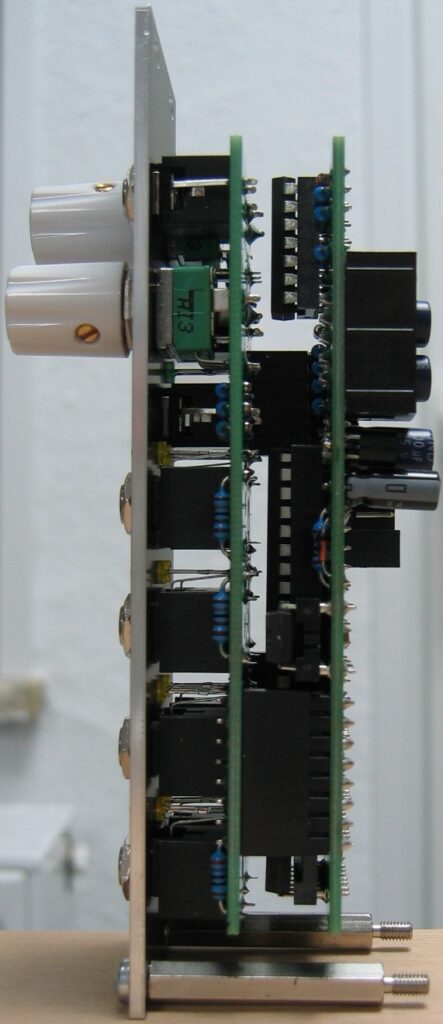
Logic I: Side view

Rotating Gate

Rotating Gate: Front view

With this module you can distribute the incoming gate or trigger up to eight outputs. The distribution is software driven. You can select the amount of the used outputs from zero to eight with a potentiometer and an input control voltage. The potentiometer voltage and the control voltage are added together. The mode potentiometer and the mode control voltage selects the algorithm for the distribution. As for the moment (2021 Nov.) only one mode is implemented. Rotating upwards. Any suggestions or programs are welcome.

Specs and features

  • Gate/Trigger distribution up to eight targets.
  • Number of used outputs voltage controlled
  • Distribution algorithm voltage controlled
  • Runs on +/-12V and +/-15V
  • Power consumption below 20mA positive rail. 5mA negative rail.

The documentation and the Gerber files for download can be found in my website.
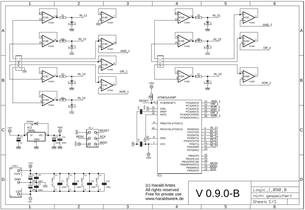
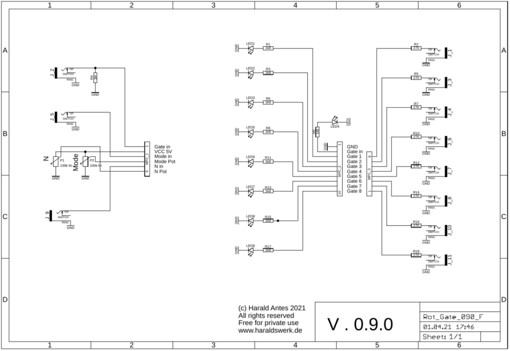
Rotating Gate: Schematic control board
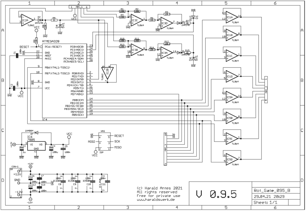
Rotating Gate: Schematic main board
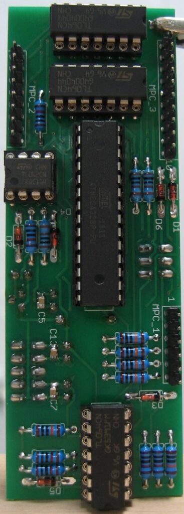
Rotating Gate: Populated control PCB
Rotating Gate: Populated main PCB
Rotating Gate: Back view
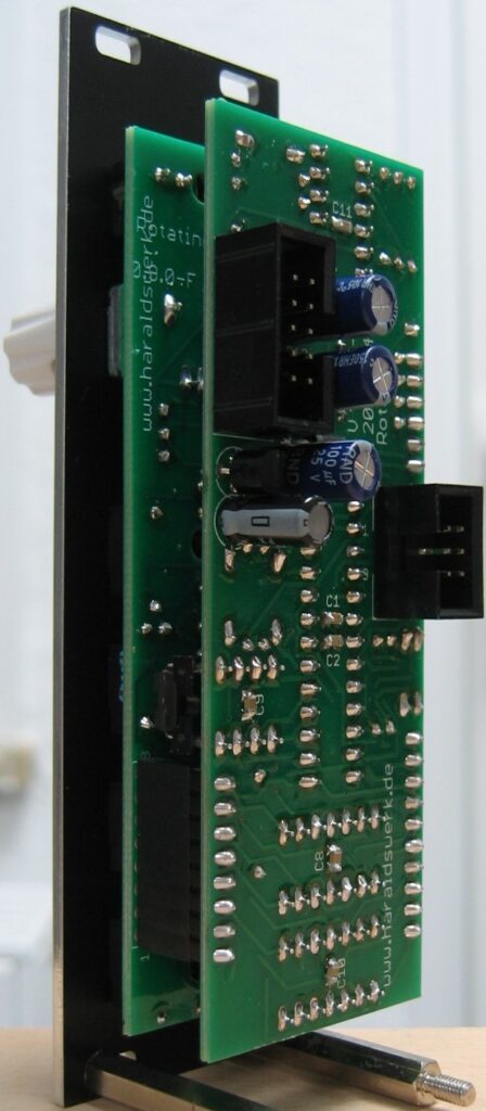
Rotating Gate: Side view

Foot switch connector

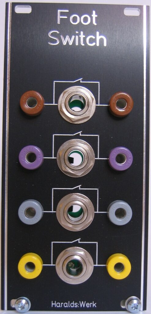
Foot swithc connector: Front view

As a Shakuhachi player I need my hands on the flute. So I use me feet to manipulate parameters and switches on the synthesizer. This module was originally build for my Shakuhachi to Synth project to provide the possibility to connect foot switches with the synthesizer and keep the patch intact when they are removed. The signal is not routed through the foot switch. Instead CMOS switches are used, turned on and off with the foot switch. So the signal stays within the synthesizer and the connection to the foot switch carries only DC. Removing the foot switch does not interrupt the signal flow in the synthesizer.

Specs and features

  • Four independent switches
  • Signal flow stays intact when foot switch removed
  • Runs on +/-15V and +/-12V
  • Power consumption below 10mA each rail

The documentation and the Gerber files for download can be found in my website.

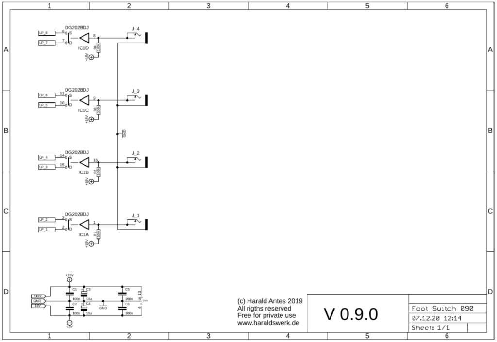
Foot switch connector;: Schematic

The switch in the DG202 is hold in on position with a 100k resistor against the positive rail. With a foot switch attached you can pull down the hold voltage when you close the foot switch.

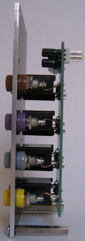
Foot switch connector: side view
Foot switch connector: Back view

Sequential Switch

Sequential Switch: Front view

Sequential Switch: Front view

This Module is build around the counter 4017. It provides you with with 8 bidirectional toggle switches. The active switch is signaled with a LED. All switches are brought out to the front panel, so you can patch this module with maximum flexibility. Audio signals are switched as well as control voltages. This module is clocked external and can be clocked with high frequencies. Way above the audio range if needed. You can select the stepped sequence length between 2..8 steps with a rotary switch. The reset input is brought out as well.
Specs and features
• Sequential switch with 2..8 steps
• Bidirectional toggle switches
• Audio and control voltages switchable
• External clock way above audio range
• Runs on +/-15V and +/-12V

The documentation for download can be found in my website.

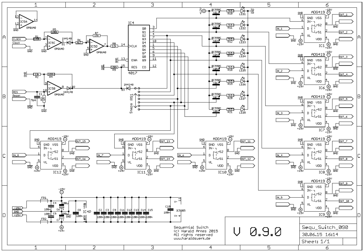
Sequential Switch: Schematic

Sequential Switch: Schematic

The 4017 is clocked through the clock input with IC5C and IC5D. RS1 selects the sequence length. The DG419 toggle switches are successive toggled with the every active step of the 4017. The LED signals the active step.

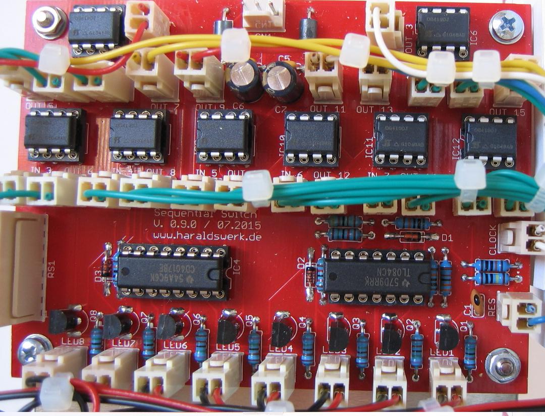
Sequential Switch: Populated PCB

Sequential Switch: Populated PCB

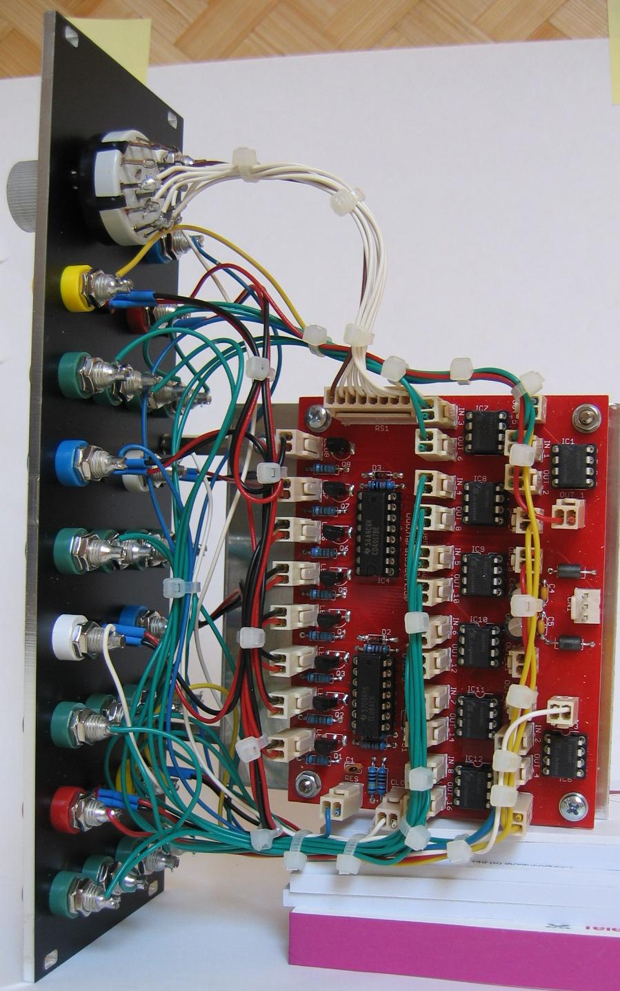
Sequential Switch: Back view

Sequential Switch: Back view