While waiting for the revised VCO PCB and still working on the details with swapping OpAmps in and out and adjusting some resistors, it’s time to talk about a bigger project. Let’s talk VOCODER!
Building a vocoder was a dream of mine for many years. There where some diy vocoders around in the late seventieth: Elektor Vocoder (10 Channel), ELRAD Vocoder (14 Channel) and ETI Vocoder (10 channels). May be some more I didn’t know. The ELRAD Vocoder used one big PCB for all filters, the Elektor Vocoder used one PCB for each filter and was build in an 19” Zoll Rack.
In 2011 Jürgen Haible designed his 20 Channel Vocoder on one big PCB. Due to his early death only a few PCB were sold. I have had only occasional contact with him. But it was inspiring to talk “synthesizers” with him. I’ll miss him. I will use some of his filter design partly in my vocoder.
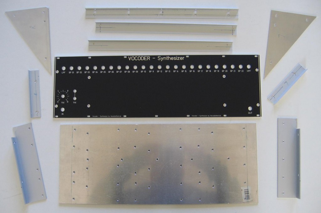
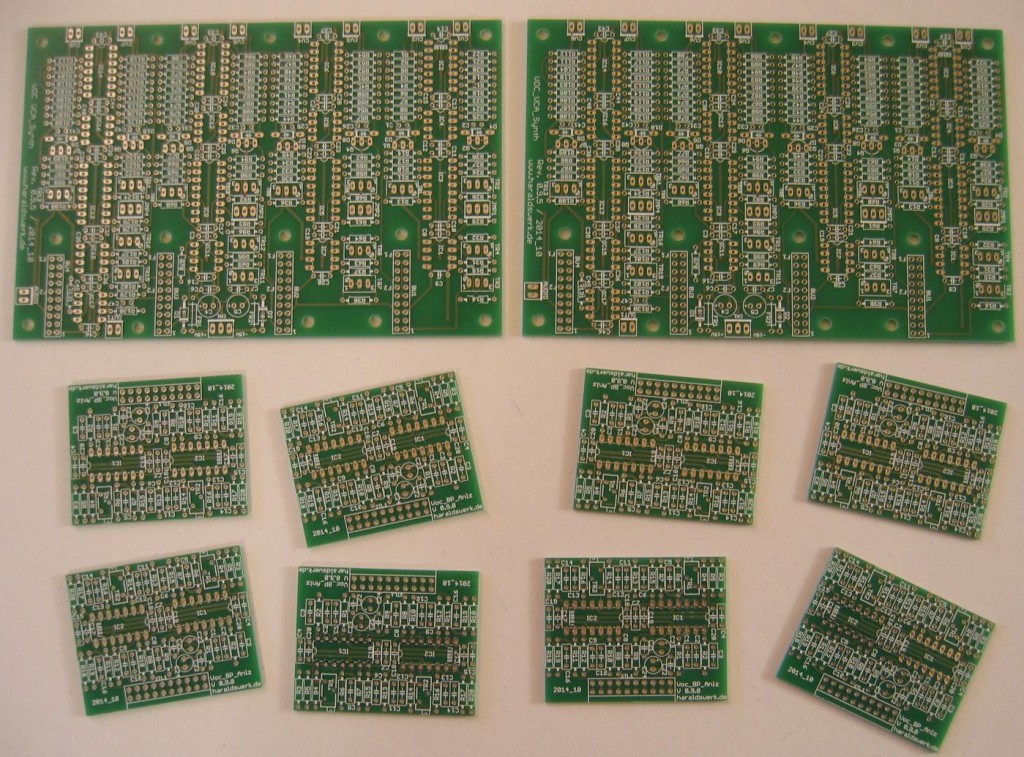
Now I heave the time and the means to design and build my own vocoder. First thought was to go the Elektor way: one channel, one PCB. Having only one big PCB seems to unflexible for me. But I want to use and explore different filter topology and frequency distributions as well. So I decided to split my vocoder in functional blocks instead of channels and make the filters pluggable. The functional blocks are divided further in 8 channels per block. So I have the flexibility of exchangeable filters and not to big PCB’s in the blocks of eight.
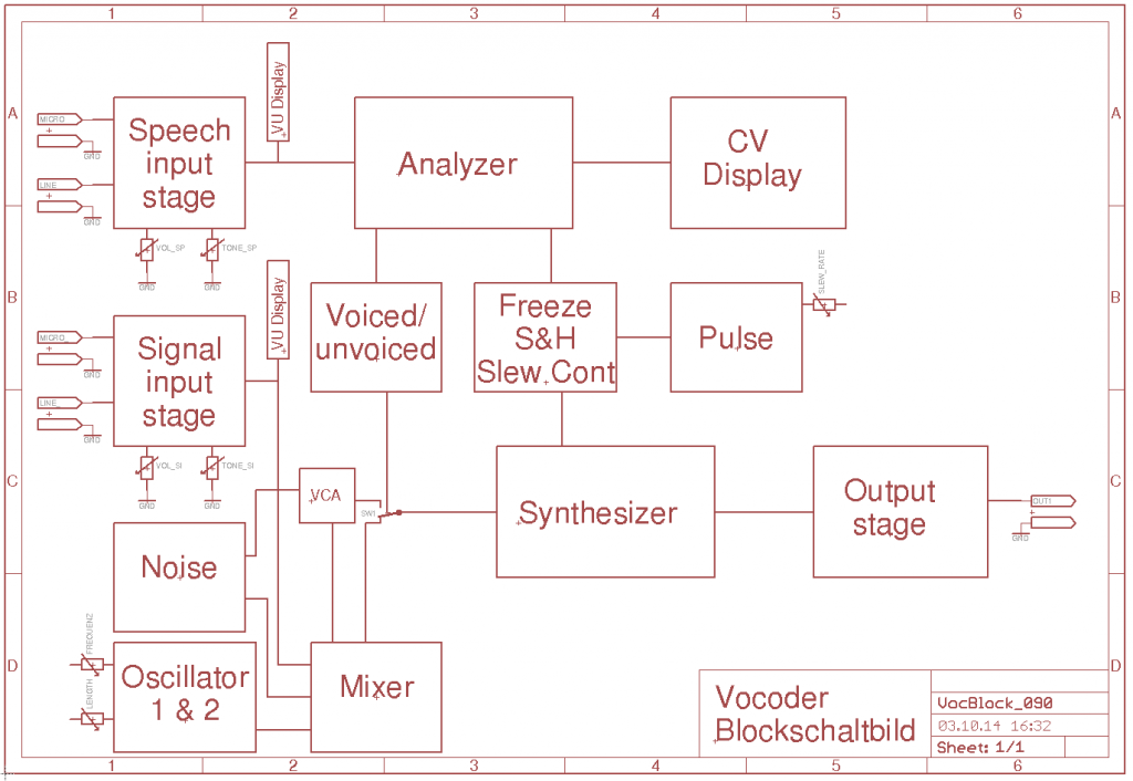
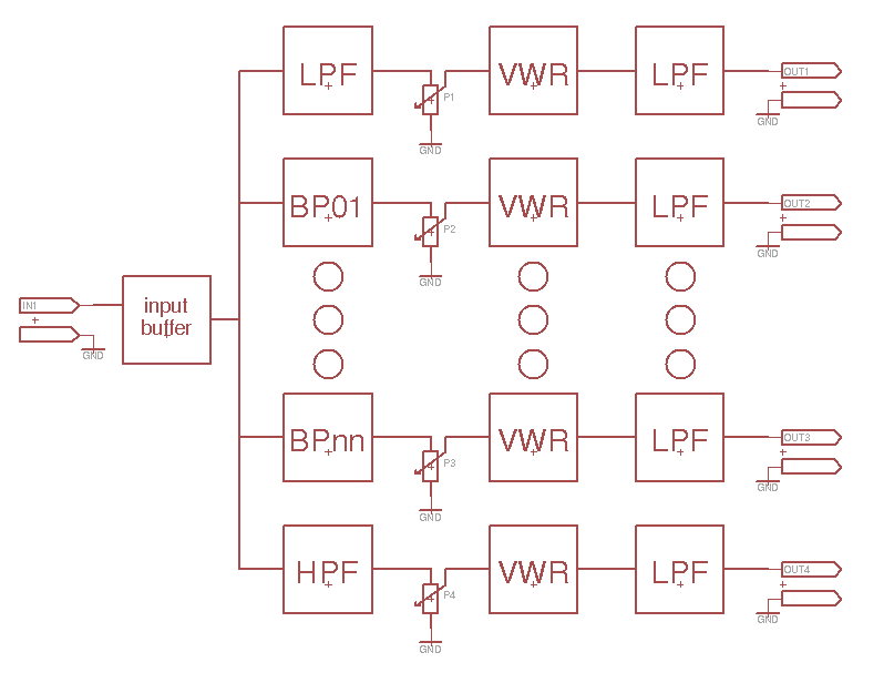
Block Diagram
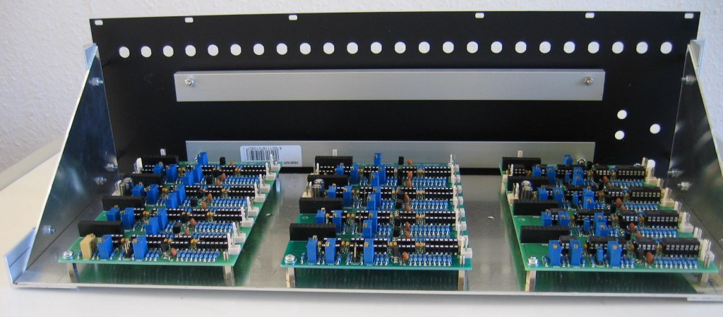
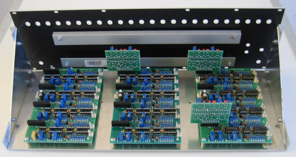
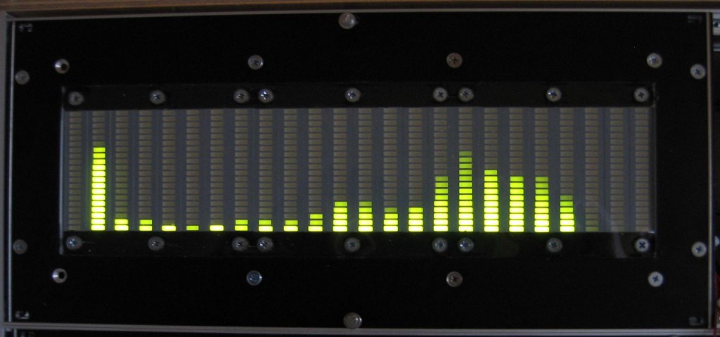
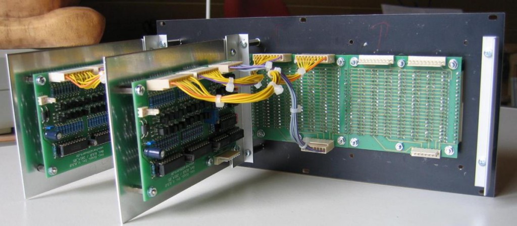
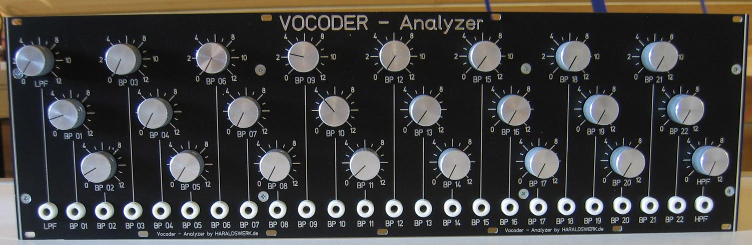
So far I have the analyzer part nearly completed, the display part completed, the synthesizer part with preliminary PCB’s running on six channels and the input stage in early prototype mode with stripboard running.
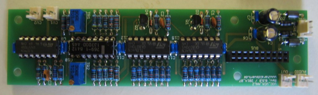
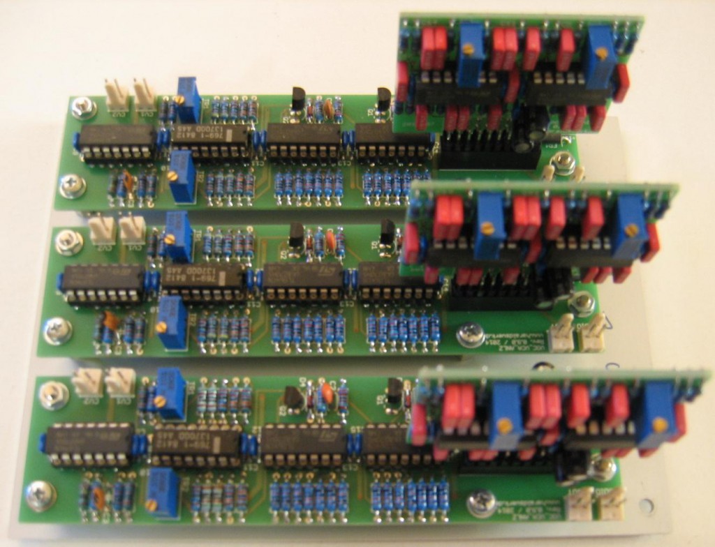
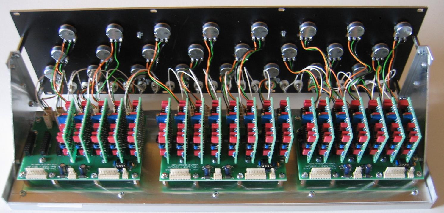
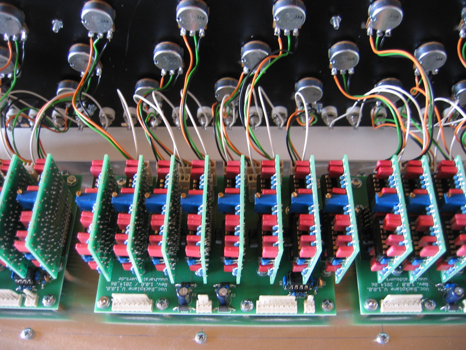
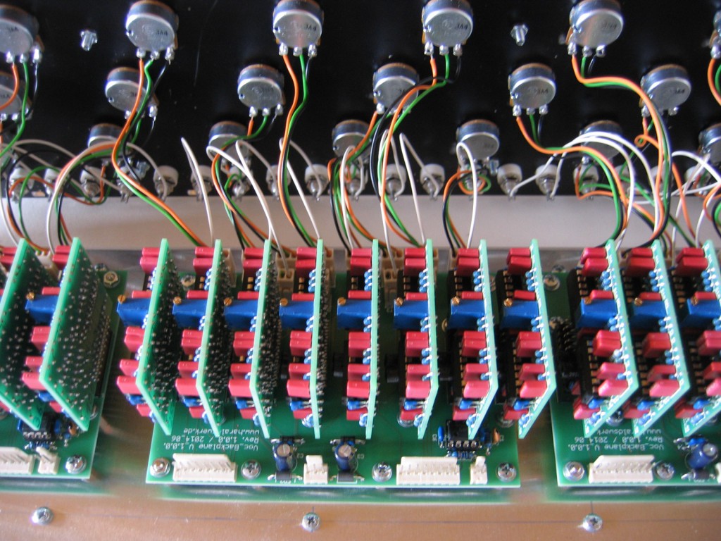 Inside analyzer
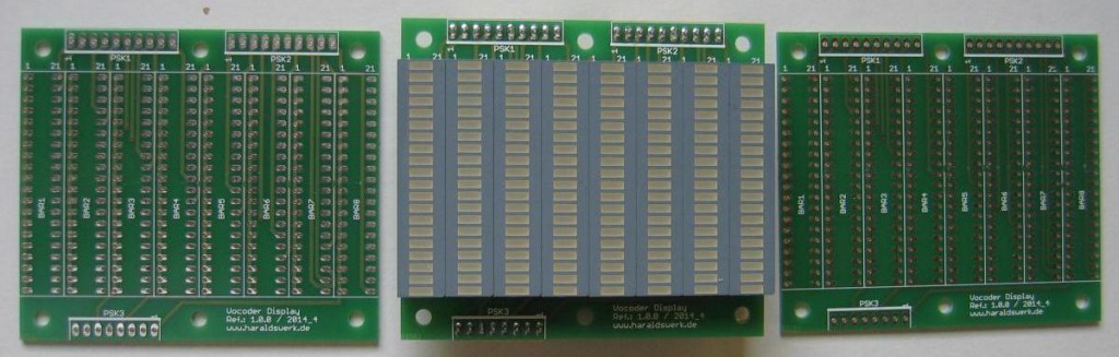
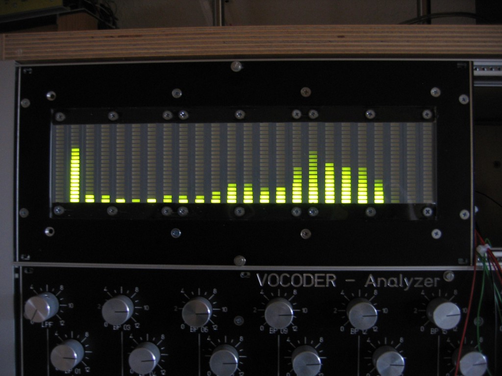 CV Display