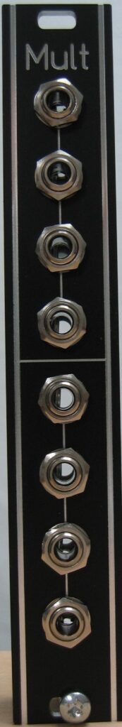
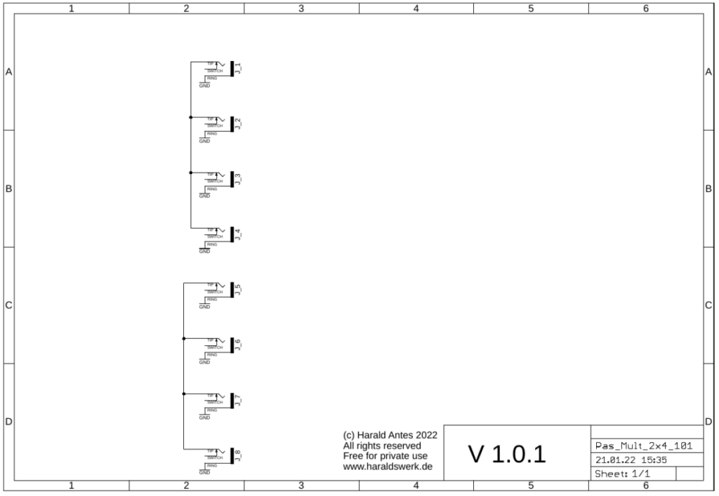
I already had a passive multiple with seven parallel in/outs. While using my synth I realized that I often use only a few of them. So I build this 2×4 multiple.
The documentation and the Gerber files for download can be found in my website.
I already had a passive multiple with seven parallel in/outs. While using my synth I realized that I often use only a few of them. So I build this 2×4 multiple.
The documentation and the Gerber files for download can be found in my website.
From time to time I want to integrate a 12V Eurorack module in my 15V banana setup. So I needed a 15V to 12V adaptor. Nothing spectacular. Just from the datasheet. This is the bigger brother for up to five modules from the single one.
The documentation and the Gerber files for download can be found in my website.
Just the standard configuration from the datasheets.
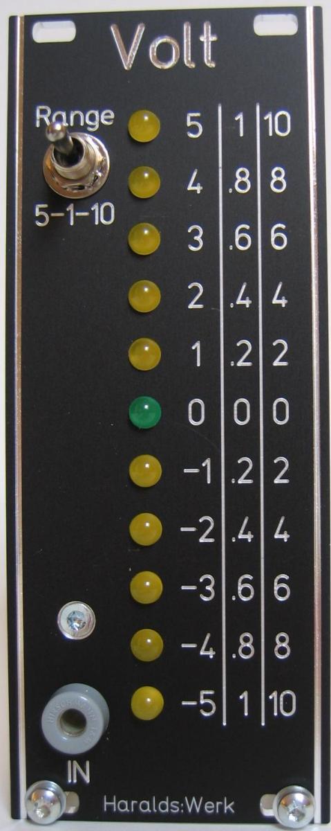
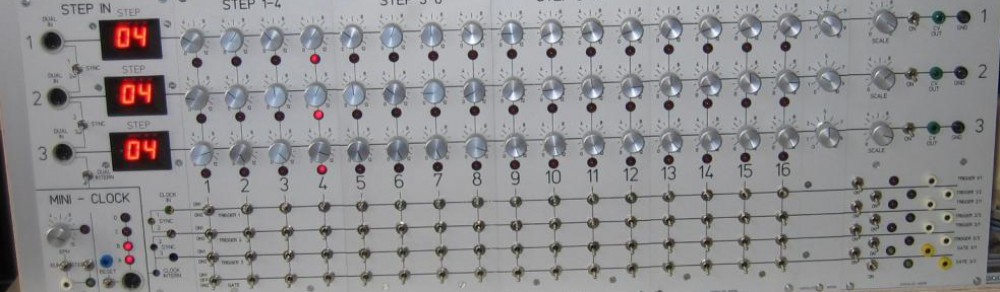
Voltmeter faceplate
The circuitry of this module was developed by Ray Wilson of MFOS. It was part of his Multi-Function Module. I have changed some resistor values to use with low current LED.
The LED voltage level meter gives you a graphical idea of where the voltage level you like to use to modulate your filter or VCA is. This circuit lights the LED in real time giving you a rough idea of the voltage level you are looking for. This is very useful when you want to move a CV from bipolar to only positive values.
Specs and features
• Three voltage ranges (+/-1V, +/-5V, +/-10V).
• Realtime LED display
• Runs on +/-15V and +/-12V
• Power consumption below 15mA each rail
The documentation for download can be found in my website.
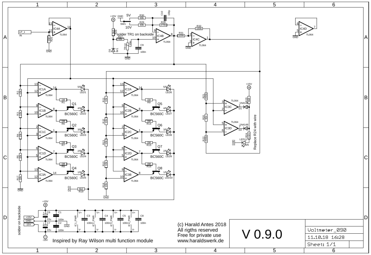
Voltmeter schematic
IC4A is used for input buffering. IC4B and IC4C and associated components build the range selection circuitry. The heart of the circuit is the group of comparators build with IC1x, IC2x, IC3A and IC3B. The left side is used to measure the positive voltage, the right side for the negative voltage. LED 11 is the “near ground” indicator. IC3C and IC3D build a window comparator. For a more detailed description please refer to the original source at Ray Wilson’s Site MFOS (Multi-Function Module).
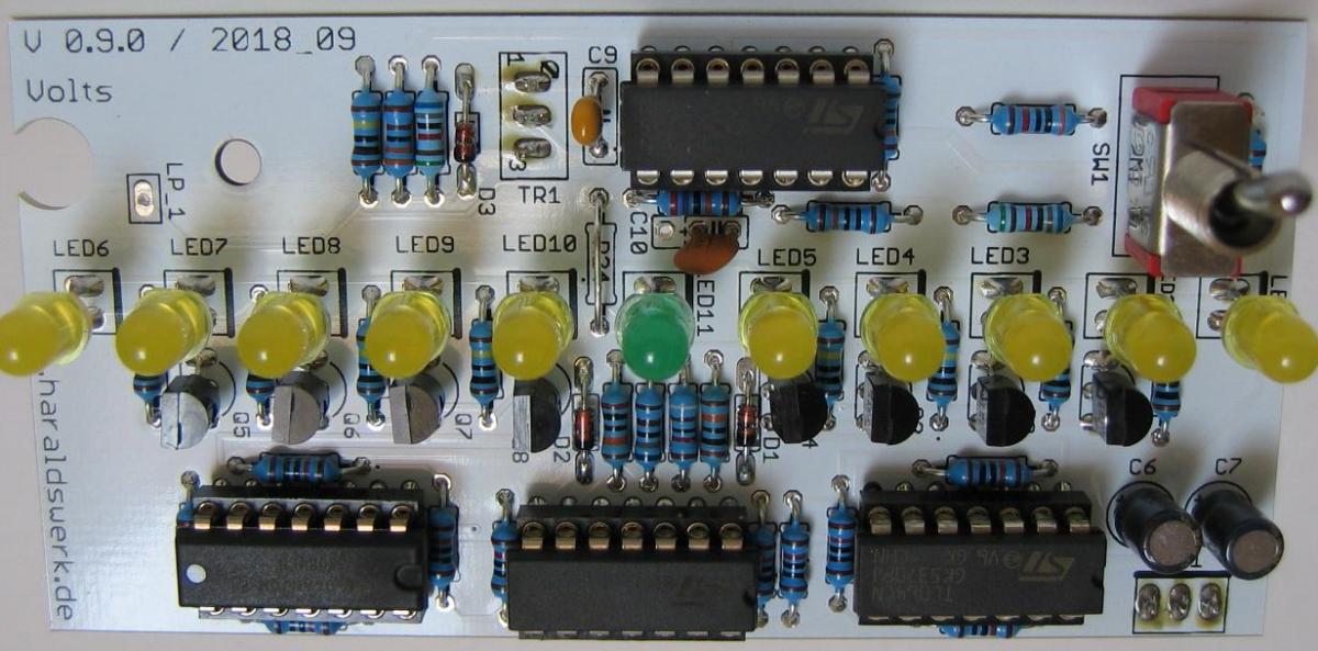
Voltmeter populated PCB
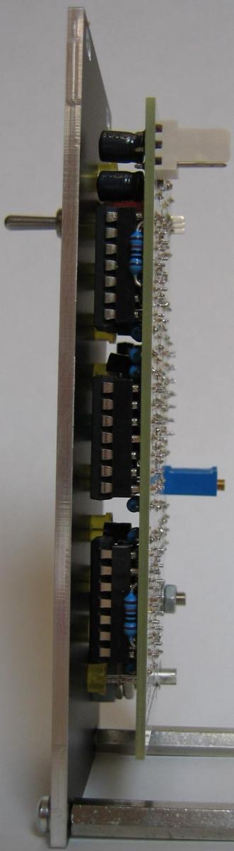
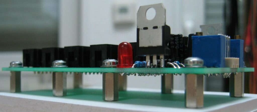
Voltmeter side view
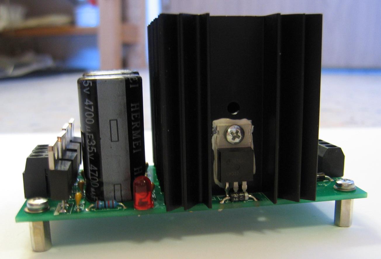
Small variable PSU with LM317 / LM337
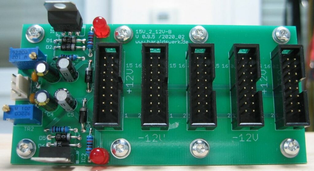
It comes in handy to have a small PSU with variable output voltages around to test modules with different voltages or drive small projects. The emphasis is on driving small projects. Tests are better done with a lab PSU. I just made a small PCB for a +/- 12..17V with LM317 and LM337. There is nothing special about it. Straight forward design. Because it is small the heatsinks are not that big and close together. Don’t drive it to hard.
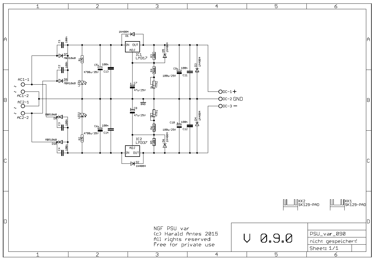
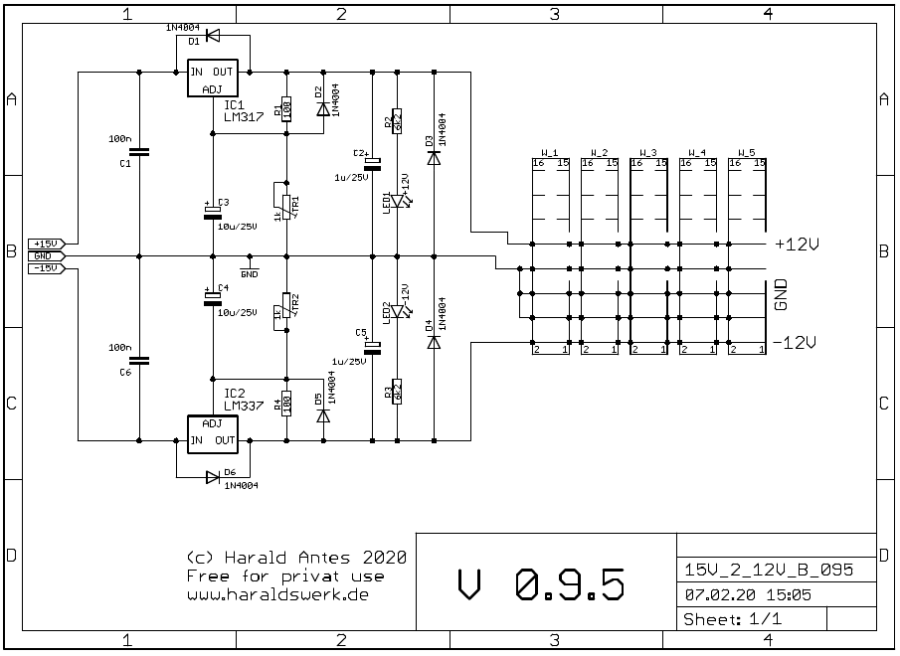
Small variable PSU with LM317 / LM337 schematic

Small variable PSU with LM317 / LM337
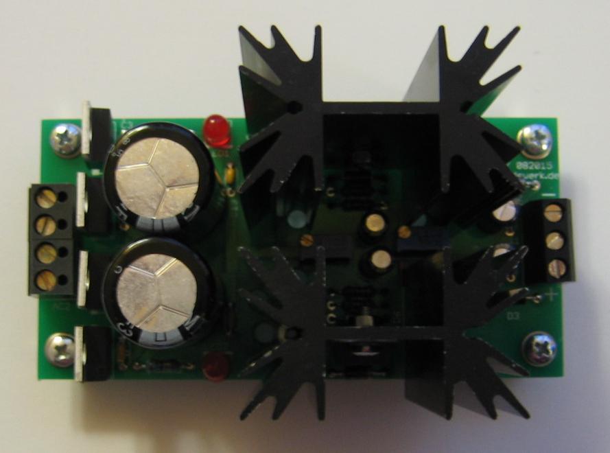
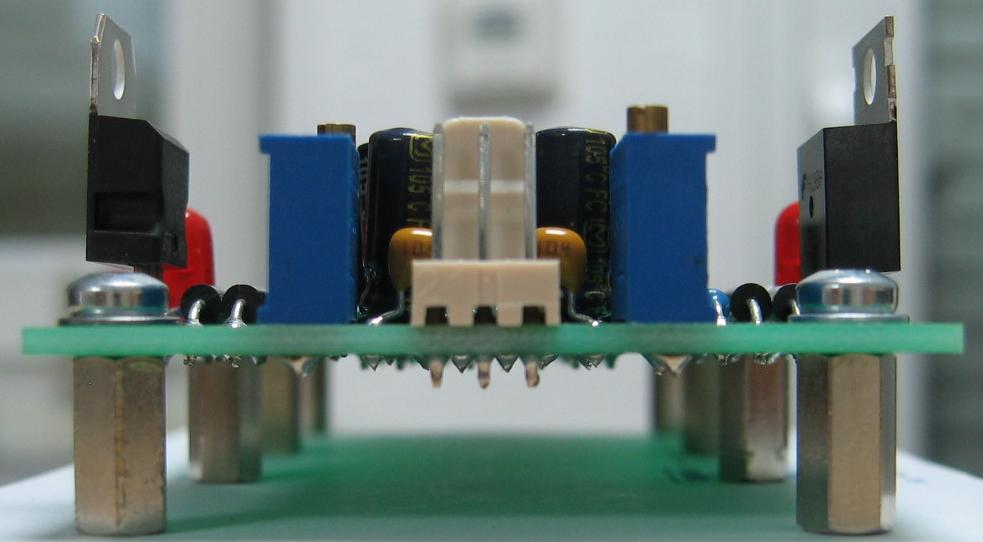
Small variable PSU with LM317 / LM337
Matched transistor-pairs are often needed while building modules for synthesizers. Especially for exponentiators and differential amplifiers. Not to forget the Moog style ladder filters. I build an transistor matcher for me many years ago and still use it. I know that there are easier matching circuits out there today but mine works great for me so there is no need to change. Mine is based on the original transistor matcher found in the “Technical Service Manual for Moog Modular Systems” on page 53. I added some circuitry for stabilizing the used voltages. That was done to be able to repeat the measurement without bothering about the power supply adjustment. We are dealing with 1mV – 2mV here!
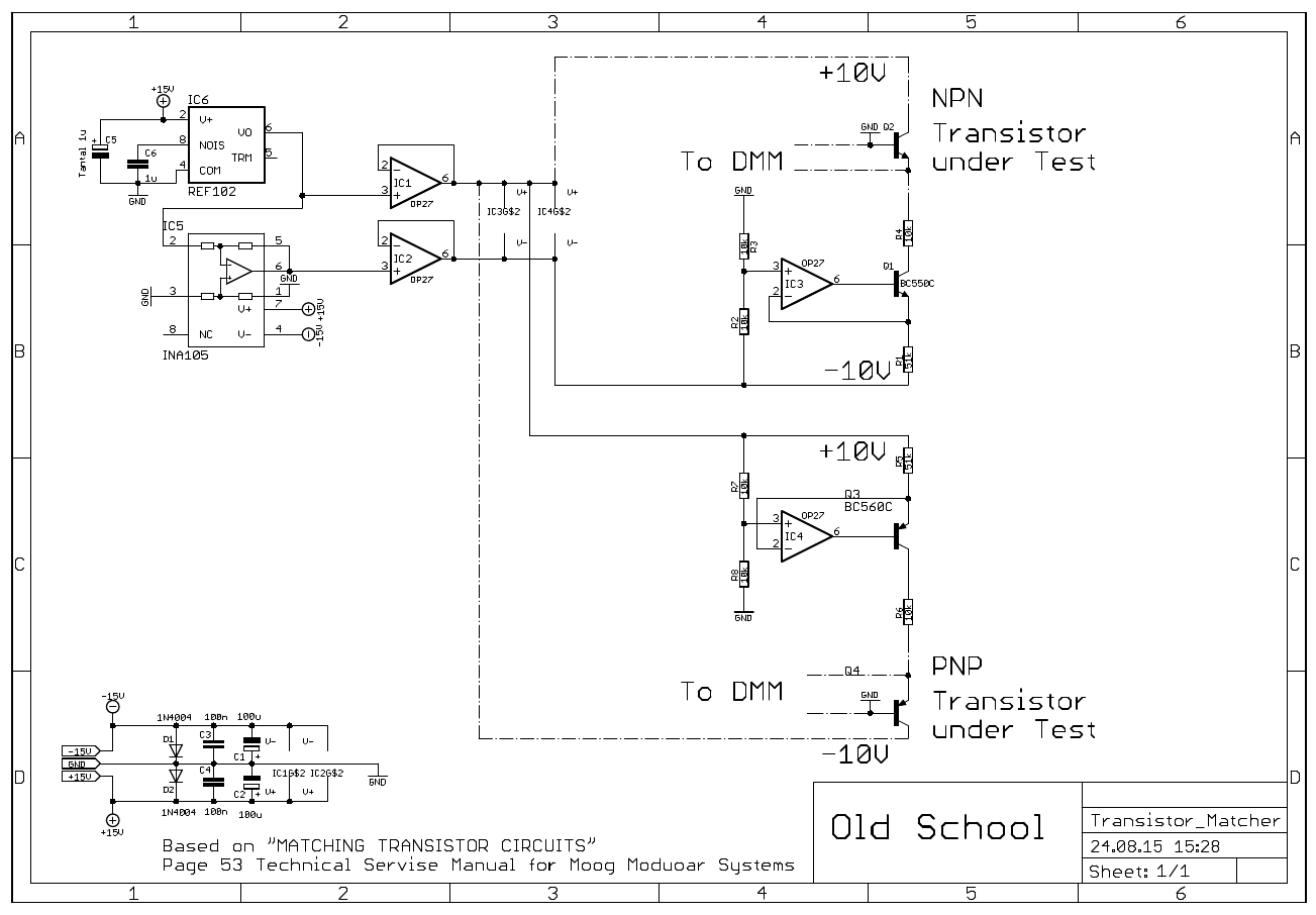
Transistor Matcher schematic
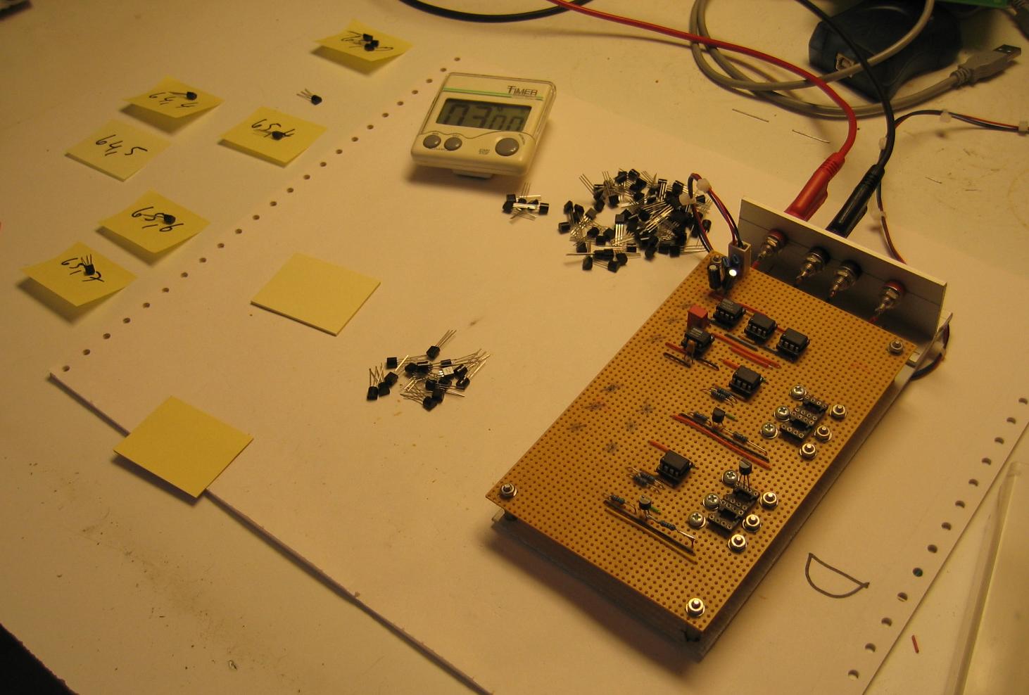
There was no need for a PCB. I just put it on perfboard and used IC sockets for the DUT.

Transistor Matcher
The usage is easy but you have to consider some precautions. The measurement is very temperature sensitive. You need to keep your environment stable. Use pliers to mount the DUT. Place the transistors into the socket. Measure base to emitter voltage. Don’t touch the transistors with fingers. The finger heat will cause the readings vary. Mark down the Vbe and find two transistors that the Vbe matches within 2mV or better.
Transistor Matcher usage
With today standards of fabrication transistors it is not unusual to find nearly every transistor within the 2mV Vbe range in a batch. You can easily match your pairs to better standards. Depending on your equipment 0.5mV Vbe match should be easily to reach. But always remember: The measurement is very sensitive. Be careful with your setup!
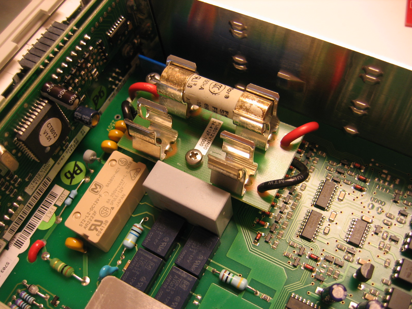
While testing a PSU I blew up the 500mA current range of my Hameg HM8012 Multimeter. Because it was a double PSU I blew two at the same time. No problem I thought. Just replace the fuses and I am done. First I looked in the manual to find out what fuses to use. To no avail. On the contrary it says: “In case of an open fuse the instrument has to be sent in for repair. A change of the fuses by the customer is not permitted”. What??! Those instruments are mostly used by tech people which know how to replace a fuse. And a fuse is for protecting the device from damage. If the device needs service after the fuse blows the fuse is near to useless. A simple replace of the fuse should do. I located the service manual and looked up what fuses to use (1A/600V 10.3x38mm).
Just open the lid:

Hameg HN8012 Multimeter lid open
Remove the fuse
Hameg HM8012 Multimeter fuse removed
Put new one in

Hameg HM8012 Multimeter fuse replaced
Close the lid. Test the device. In my case the fuse worked as intended. No damage done to the Hameg HM8012 Multimeter. And no need to send it in for service ($$$).
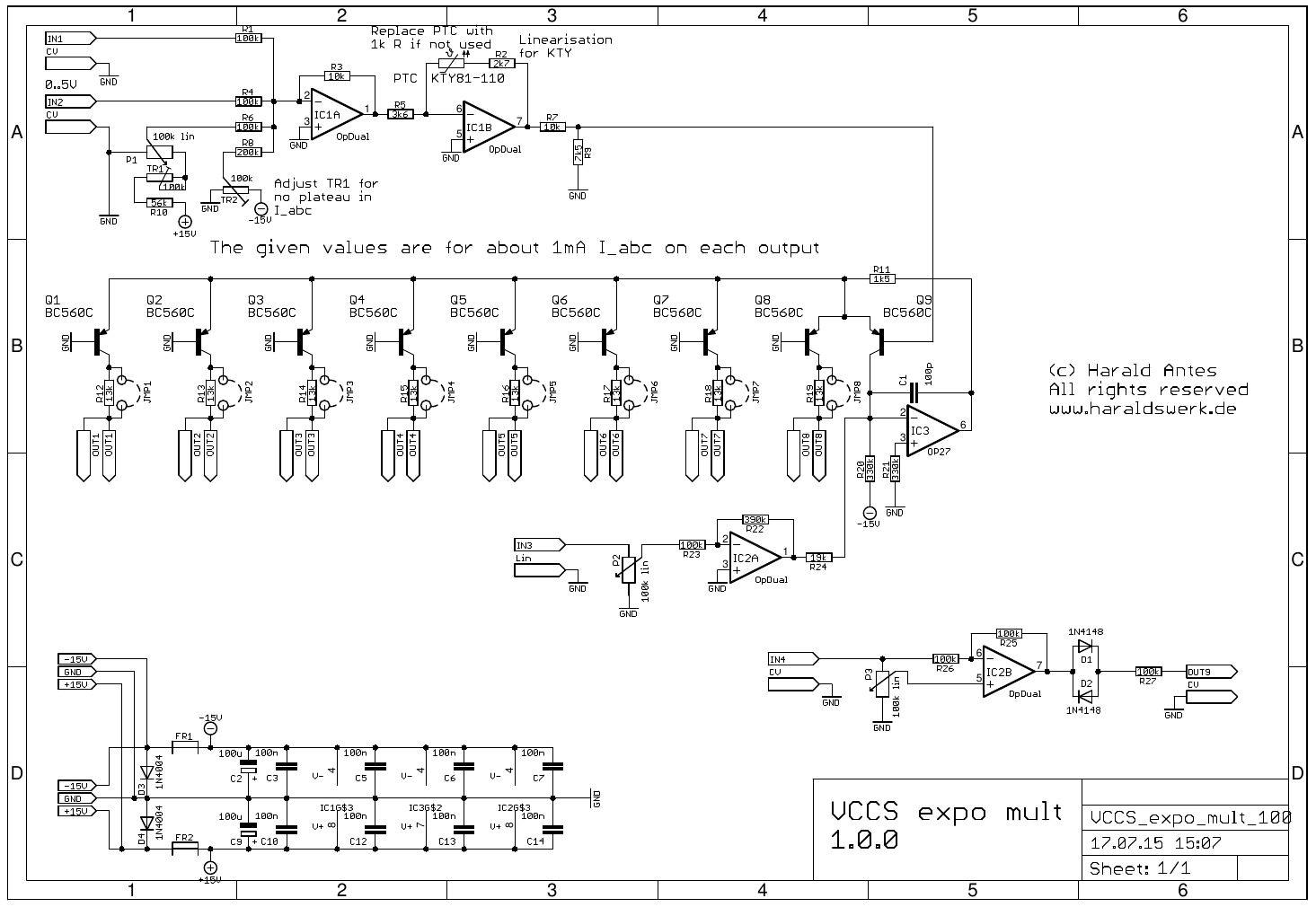
Multiple voltage controlled logarithmic current sources are often needed when developing new modules. They are standard building blocks of nearly every VCF and VCA. And useful when the Gm of OTA’s must be checked or matched. So i thought it comes in handy to have just such a current source around as a “module” when needed. I designed a schematic and a small PCB with eight current outputs. It can manually operated with a potentiometer and modulated with an external voltage as well. I added a linear voltage input and a sign changer. The sign changer is very useful when testing a HPF which needed reversed CV voltage to operate properly. The output current is limited with the output resistors. Increasing this resistors lowers the maximum output current. If you already have current limiting resistors in your module under test, you can bypass the build in resistors with jumpers.
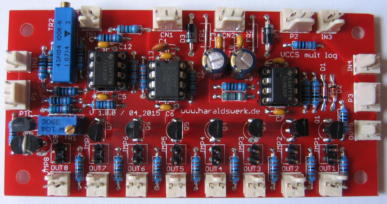
Logarithmic voltage controlled current source
Logarithmic voltage controlled current source
IC1A acts as a voltage adder. IC1B with the KTY81-110 is used for temperature compensation. It can be replaced with a 1k resistor if not needed. R2 is needed for linearizing the KTY81. Q9 Q8 and IC3 builds the exponentiator and current source. Q1 to Q7 are the additional outputs. R12 to R19 limits the maximum current. Increasing their values lowers the maximum current. IC2A serves as linear input. The sign changer is build around IC2B.
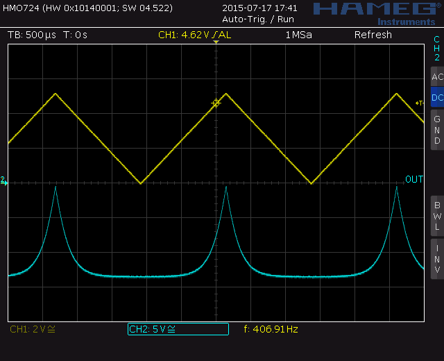
Logarithmic voltage controlled current source. Right calibration.
If you do the calibration correctly you can see a sharp peak at the logarithmic curve. The procedure is described on my website.
While waiting for the PCB’s to connect my Kimber Allen contacts to the electronics of the keyboard scanner I worked on my long planned 36dB VCF. I wanted a replacement and additional VCF for the original 24dB Elektor Formant filter. I kept the original structure and just added two more 6 dB filter cells. The emphasis (Q) is now voltage controlled. I added a linear timbre modulation and a “gender changer” for the ENV pot for better usage as well. And I replaced the mechanical LP/HP switch with electronic switch DG419. Maybe I am looking in 48dB next time not knowing if this makes sense musicaly.
To start I tested one 6dB cell with one half or a LM13700 and the DG419 switch on breadboard.

VCF 6dB cell on breadboard
Drawing the schematic:
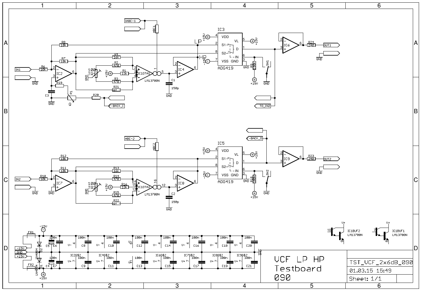
VCF 2x6dB schematic
Next was to make some PCB with two 6dB cells each.
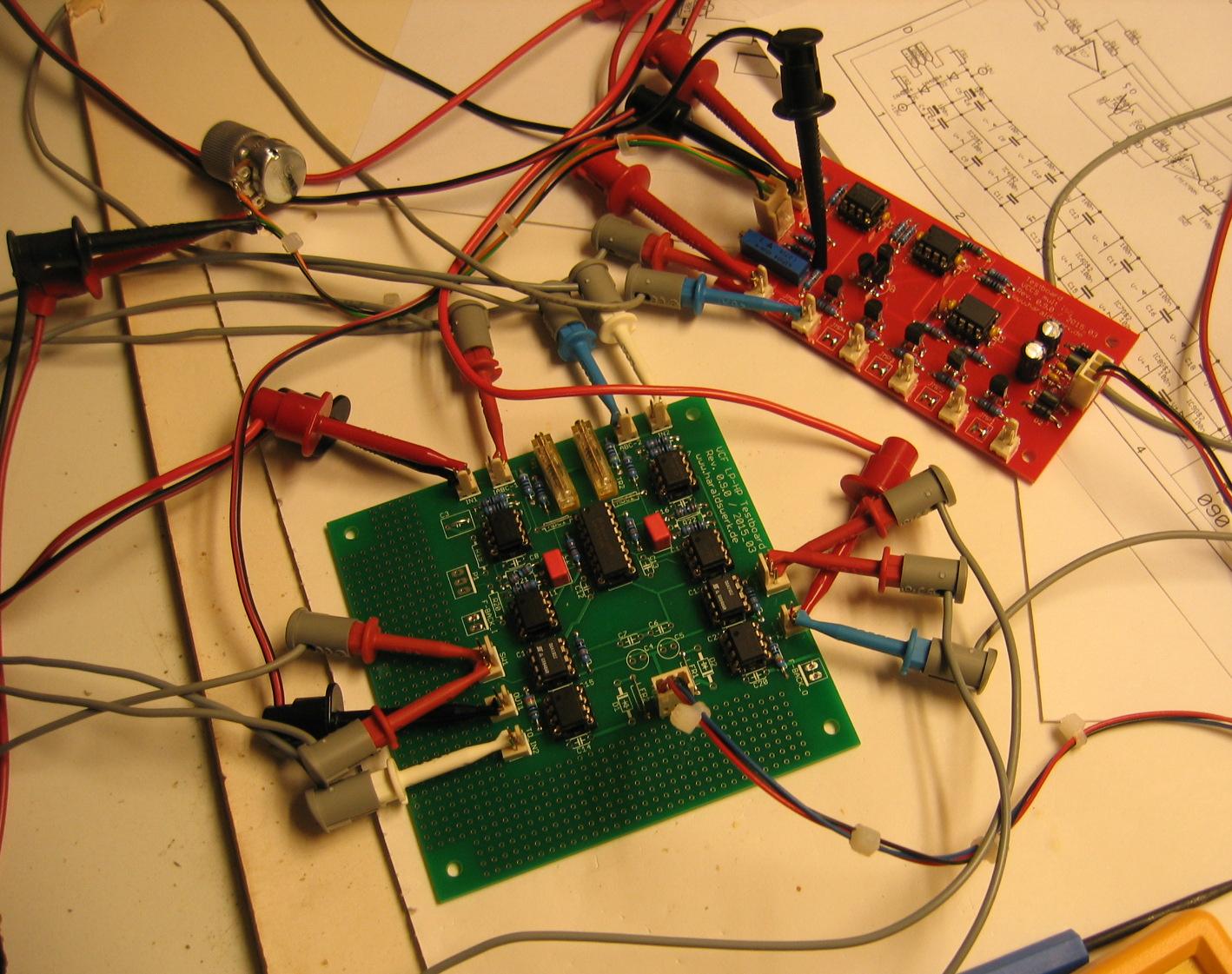
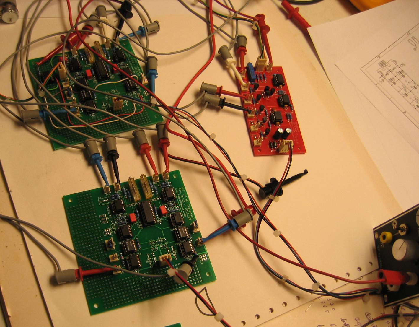
VCF 2x6dB cell PCB
The red PCB on the picture is a prototype of a logarithmic voltage controlled current source with multiple outputs (Will come later in this blog). The green PCB is the filter. Those two 6dB cells makes quite a good 12dB VCF like the original 12dB Elektor Formant filter.
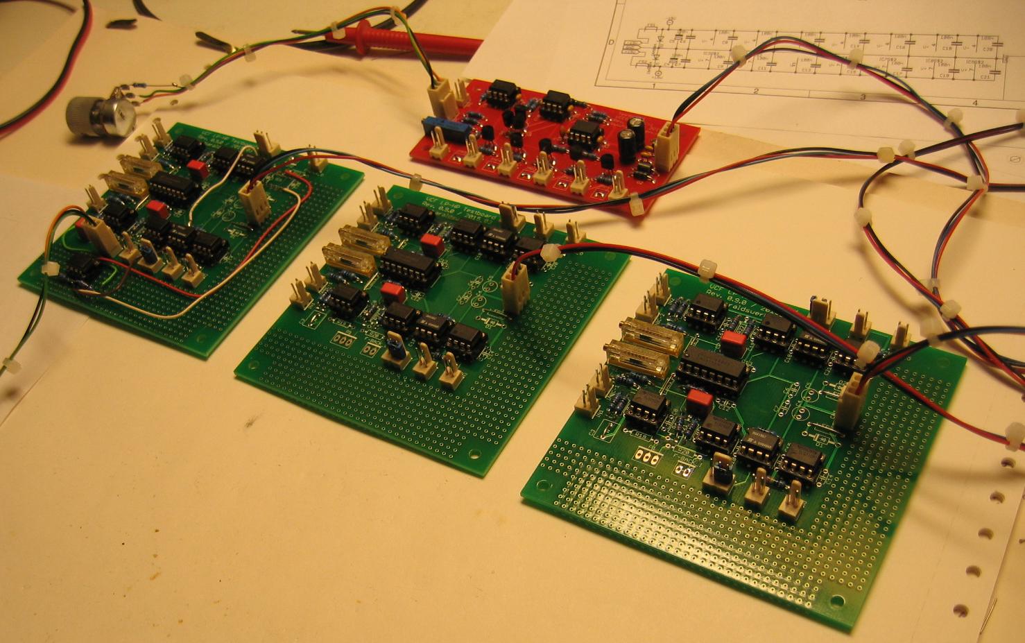
Adding two more for 24dB
VCF 24dB
Those four 6dB cells makes quite a good 24dB VCF like the original 24dB Elektor Formant filter.
Adding two more for 36dB
VCF 36dB
Putting it together and adding the voltage controlled feedback path(Q). The feedback path was added with means of the partly stuffed blue PCB. This one contains the prototype of my implementation of the Moog ladder filter, where I will use the same feedback technique (More in a later blogpost).
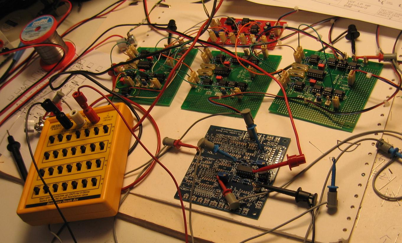
VCF 36dB with feedback
Building a ADSR or LFO with certain features can become very complex and costly. And there are features that can not be realized at all. Like special waveforms. Other functions are hard to realize in the analog domain. So i wanted to experiment with a microprocessor in the digital domain. To start with i build a testboard around the ATMega328p and the 12bit analog to digital converter MCP4921. I added some hardware features that i found might be useful.

ATMega328p Testboard with MCP 4921
Analog inputs: 4Pots 2CV
CV inputs with selectable threshold +2.5V/+5V
Several digital inputs for switches.
Two digital inputs normalized to 5V with overvoltage protection
Analog output with 12bit DAC MCP4921</li>
Analog output switchable 0..5V / 0..10V / -5V..+5V
2 LED for visualizing analog output
External clock 20MHz
External voltage reference
ISP
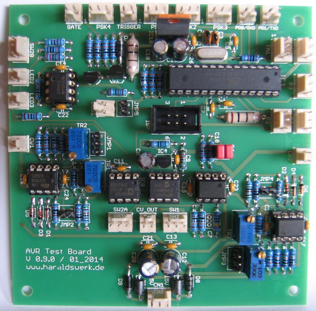
ATMega328p Testboard with MCP4921 PCB
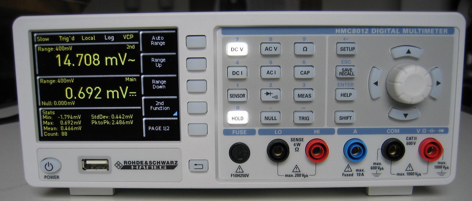
My new digital bench multimeter arrived today. It is a HMC8012 Hameg by Rohde & Schwarz.
|
5 ¾-Digit Display (480,000 Counts) |
|
|
Simultaneous Display of 3 Measurements, e.g. DC + AC + Statistics |
|
|
Up to 200 Measurements per Second |
|
|
DC Basic Accuracy 0,015% |
|
|
12 Measurements Functions: DCV, DCI, True RMS, ACV and ACI, Frequency, 2- and 4-Wire Resistance, Capacitance, Continuity,Diode Test, Temperature, Power |
|
|
Crisp color TFT display for excellent readability |
|
|
Resolution: 1μV, 100 nA, 1mΩ, 1pF, 1Hz, 0,1 °C |
|
|
True RMS Measurement AC, AC + DC |
|
|
Mathematic Functions: Limit Testing, Minimum/Maximum, Average, Offset, DC Power, dB, dBm |
|
|
Temperature Measurements with Platinum Sensors (PT100/PT500/PT1000) |
|
|
Data Logging in .CSV-Format to Internal Memory or USB-Stick |
|
|
Interfaces: USB-TMC and Ethernet (LXI 1.4 Core), optional IEEE-488 (GPIB) |
|
|
SCPI commands widely compatible with Agilent 34410A |