While waiting for the PCB’s to connect my Kimber Allen contacts to the electronics of the keyboard scanner I worked on my long planned 36dB VCF. I wanted a replacement and additional VCF for the original 24dB Elektor Formant filter. I kept the original structure and just added two more 6 dB filter cells. The emphasis (Q) is now voltage controlled. I added a linear timbre modulation and a “gender changer” for the ENV pot for better usage as well. And I replaced the mechanical LP/HP switch with electronic switch DG419. Maybe I am looking in 48dB next time not knowing if this makes sense musicaly.
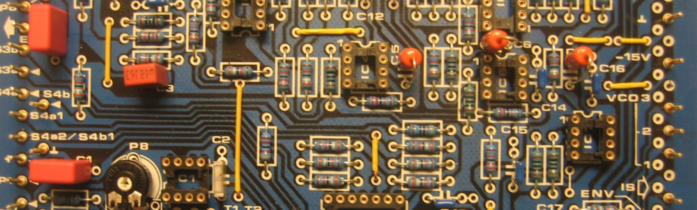
To start I tested one 6dB cell with one half or a LM13700 and the DG419 switch on breadboard.

VCF 6dB cell on breadboard
Drawing the schematic:
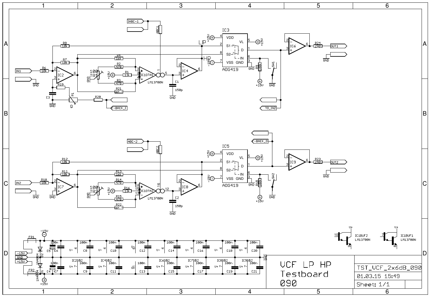
VCF 2x6dB schematic
Next was to make some PCB with two 6dB cells each.
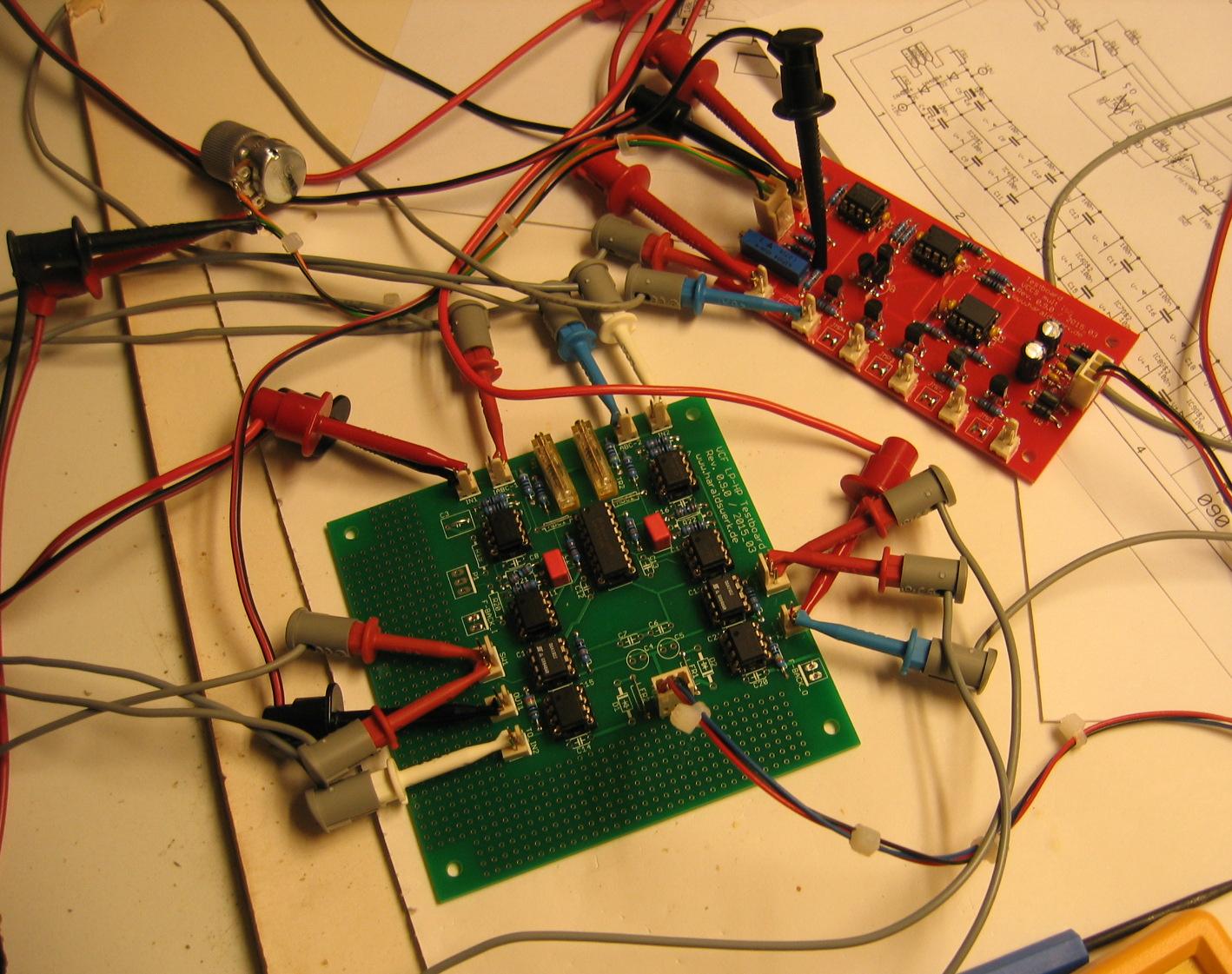
VCF 2x6dB cell PCB
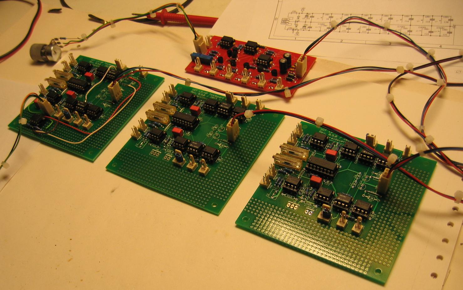
The red PCB on the picture is a prototype of a logarithmic voltage controlled current source with multiple outputs (Will come later in this blog). The green PCB is the filter. Those two 6dB cells makes quite a good 12dB VCF like the original 12dB Elektor Formant filter.
Adding two more for 24dB
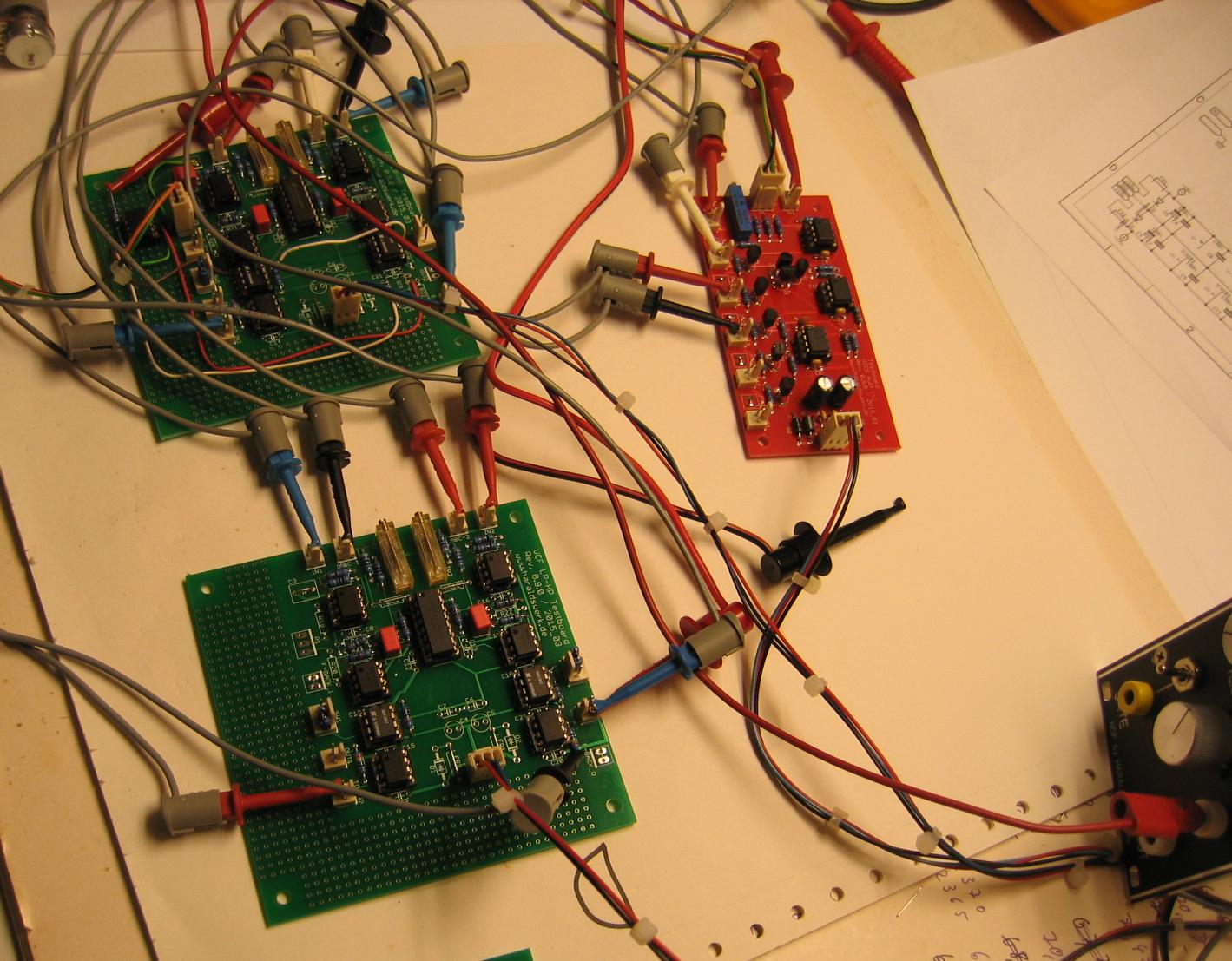
VCF 24dB
Those four 6dB cells makes quite a good 24dB VCF like the original 24dB Elektor Formant filter.
Adding two more for 36dB
VCF 36dB
Putting it together and adding the voltage controlled feedback path(Q). The feedback path was added with means of the partly stuffed blue PCB. This one contains the prototype of my implementation of the Moog ladder filter, where I will use the same feedback technique (More in a later blogpost).
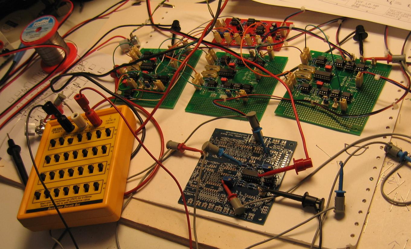
VCF 36dB with feedback