Here is a small weekend PCB project. A quad gate to trigger converter.
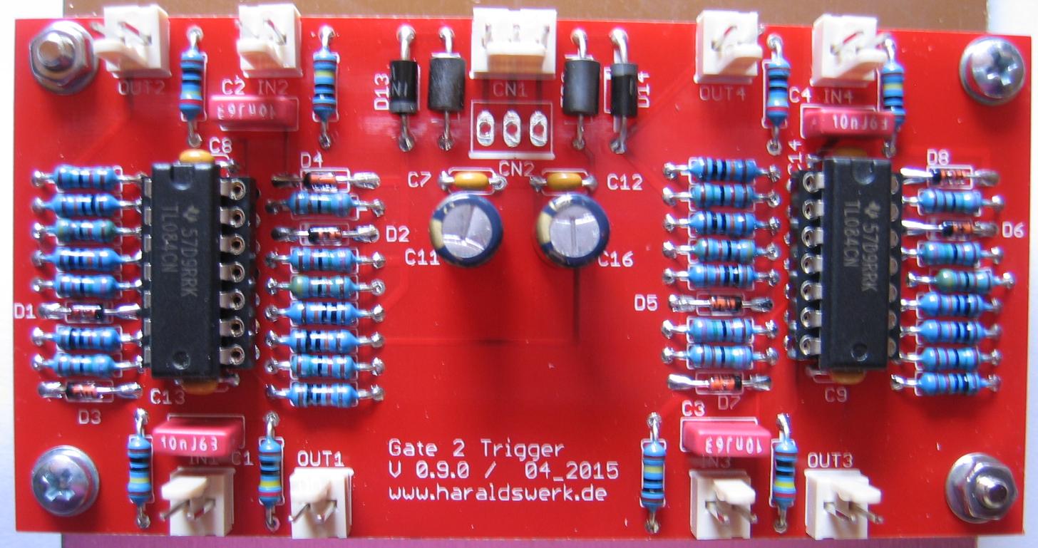
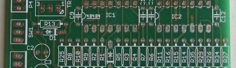
Gate to Trigger Converter PCB
A gate to trigger converter can be used in multiple ways. This device can not only convert gate to trigger signals. It converts any fast enough rising positive edge from a signal in a trigger pulse. The trigger pulse length is independent from the input signal. The trigger length is determined by one capacitor and is easily adjusted to your needs.
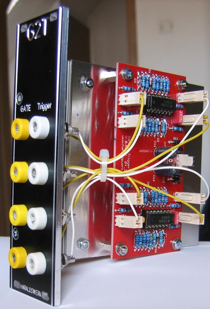
Gate to Trigger Converter – Module
Those four gate to trigger converter are functionally identical. The input network converts a fast enough rising edge of a positive going signal into a brief positive going pulse. The following op-amp wired as comparator cleans the resultant pulse and forms a square pulse. The second stage cuts of the negative part, shift the output level down to 5V and buffers the output. The trigger pulse lengths is adjusted be changing the value of the input capacitor. The output level can be adjusted with the voltage divider at the output of the first op-amp.
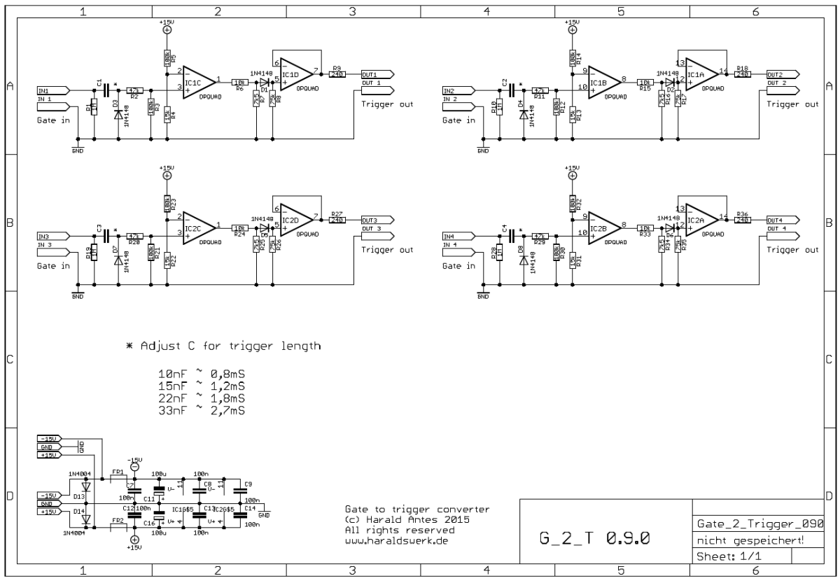
Gate to Trigger Converter – Schematic
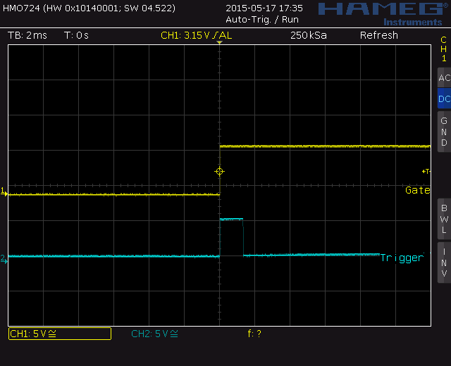
Gate to Trigger Converter – Screenshot