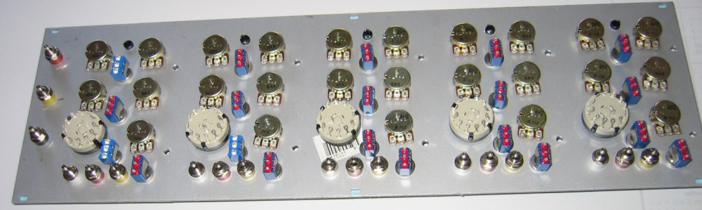
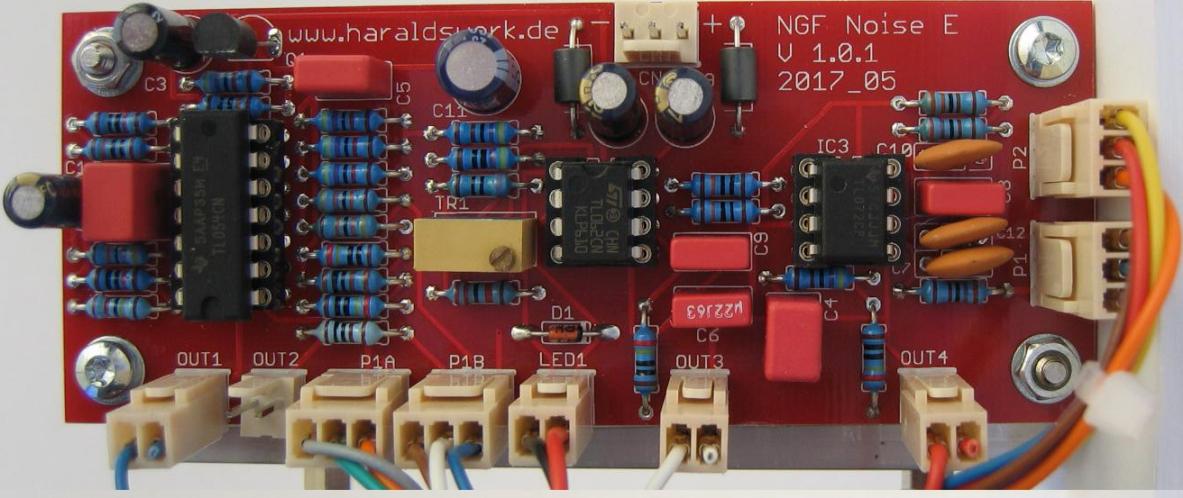
NGF-E Project: White and coloured noise, random voltage PCB
This is the noise module for my Next Generation Formant project. It is a combination of two original Elektor Formant modules. The Noise module from Elektor Formant book one and the Coloured Noise (CNC) module from book two. It provides a white noise output, a fixed coloured noise output, a variable coloured noise output “red” “blue” and a random voltage output. The noise is derived from the reverse biased BE diode of an NPN transistor.
The documentation for download can be found in my website.
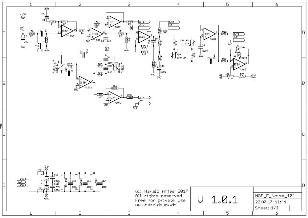
NGF-E Project: White and coloured noise, random voltage schematic
Noise source is the reverse biased BE diode of NPN transistor Q1. The following operational amplifier IC1A and IC1B amplifies the noise to 10Vpp. IC1C is the buffer for the white noise output. The high pass filter C5/R23 and R13/R19 in the feedback loop of IC1D provides a bass boost for the fixed coloured noise output. IC2B is configured as a 12dB low pass. So you get a low frequency random voltage. The changing speed is set with P1A/P1B which sets the corner frequency of the low pass filter. IC2A / LED1 makes the fluctuation visible. Tr1 adjust the brightness of LED1. In the feedback loop of IC3B is an adjustable filter combination which gives you a wide range of adjustable coloured noise with P1 and P2. The output is buffered with IC3A.
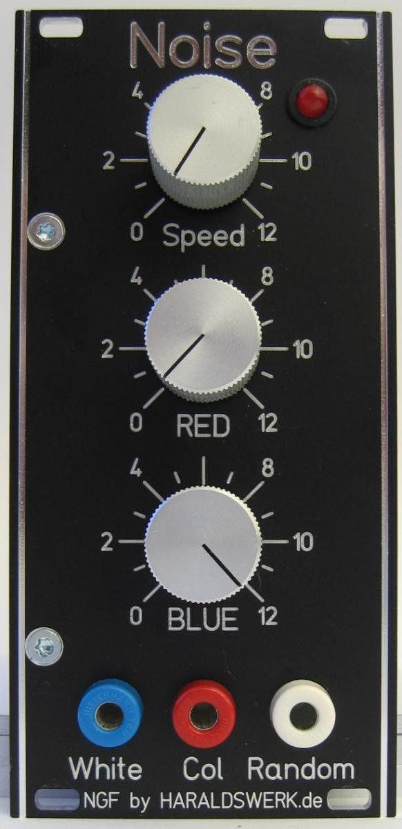
NGF-E Project: White and coloured noise, random voltage faceplate
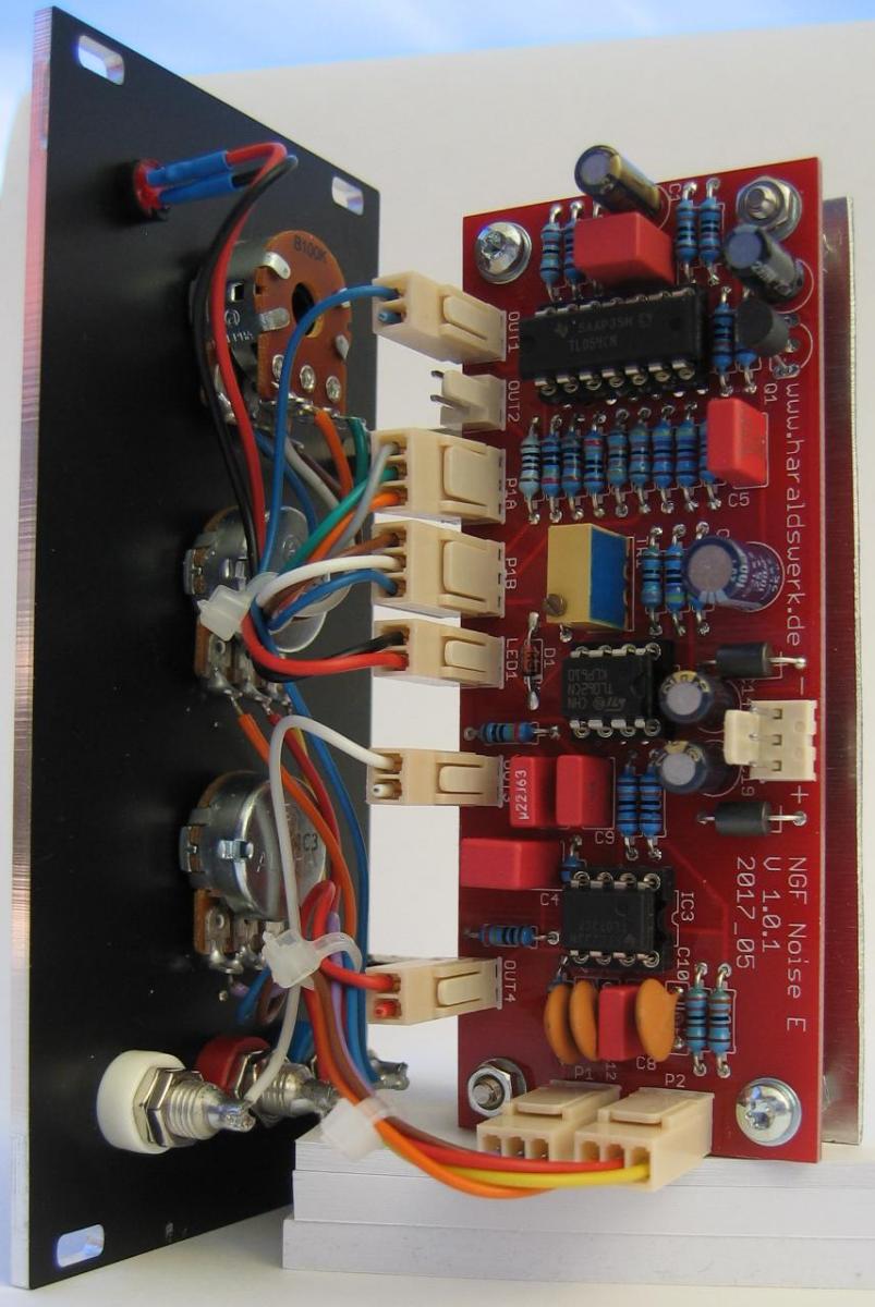
NGF-E Project: White and coloured noise, random voltage
Hi Harald!
The transistor is specially selected or we just grab a random one and use the R8 trick?
Hallo Isidoro,
it is recommended to select the transistor for best results. I just picked a random one and it worked fine. I think adjusting R8 and the amplification of IC1A with R1/R2 is the easiest way to go.
Best
Harald