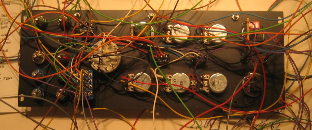
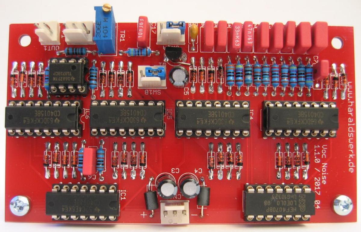
NGF Vocoder: Pink and white noise source PCB
Here is the noise module for my Vocoder project. This noise generator is not only useful for the vocoder but also for various other audio and acoustic measurements. The output can be switched between white and pink noise. The pseudo random noise is produced with the aid of a 31 bit shift register. Zero inhibit technique is used. This design follows closely the original from the Elektor magazine.
The documentation for download can be found in my website.
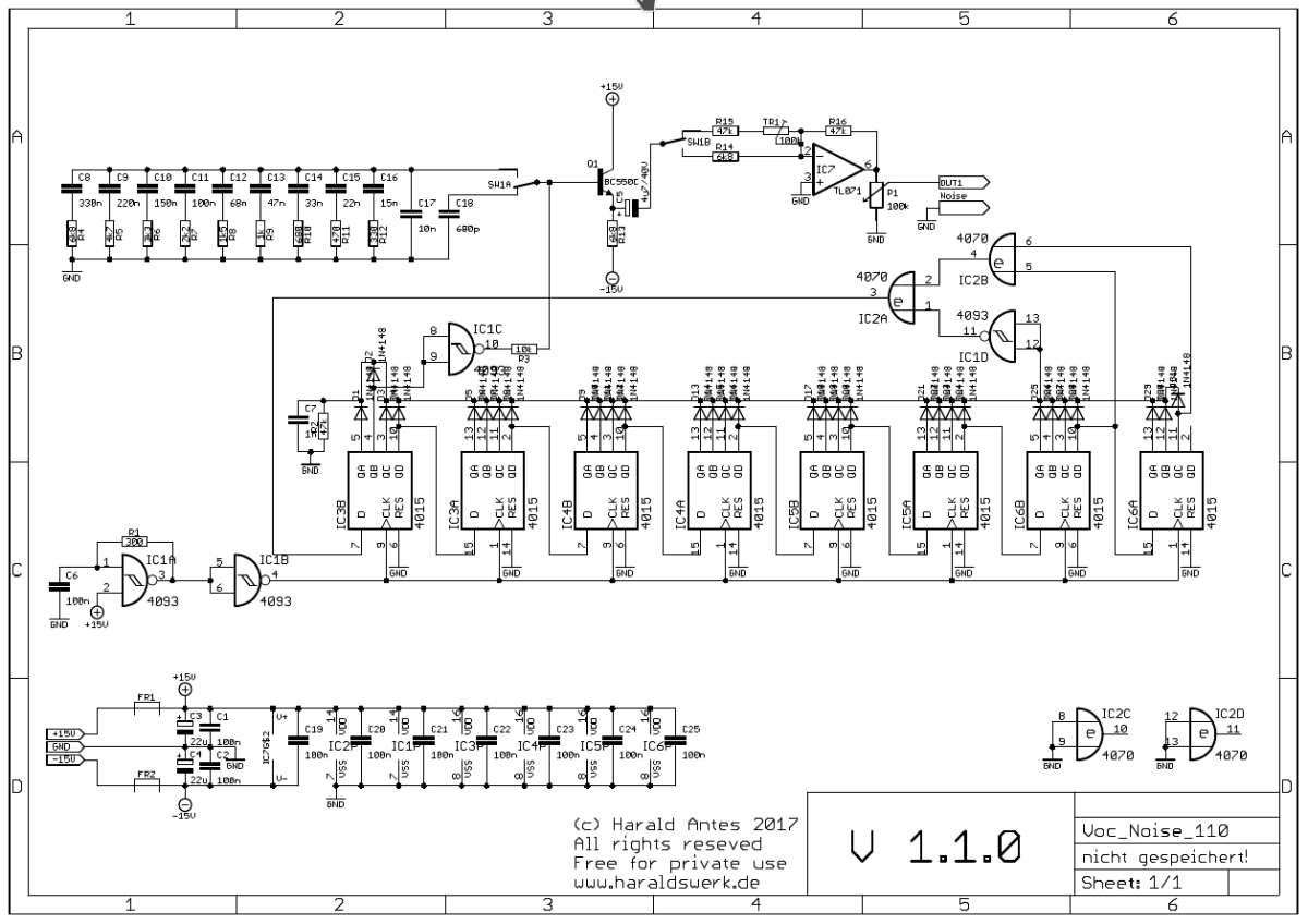
NGF Vocoder: Pink and white noise source schematic
IC1A and IC1B together form the clock generator. Diodes D1..D31 combined with IC1D provide the zero inhibit. As soon as the “000…0” state occurs, a “1” is entered in the shift register by way of IC2A. Gate IC2B makes sure outputs 28 and 31 of the shift register are EXOR back coupled. IC1C is the buffer before the filter which can be switched to pink and white noise. The white noise filter is a low pass filter of about 23kHz with 6dB slope. The pink noise has to be slightly more amplified than the white. TR1 is used to equalise the output voltage for pink and white noise.