This is the software driven replacement for my all hardware pitch to voltage converter from my Shakuhachi to Synth project. The software driven approach has the advantage of easily adaption for different frequency ranges. In my case it is the range of the Shakuhachi. To change the range just adapt the software. It is completely temperature independent. The needed input is a pulse train derived from your original signal. You can use my Signal to Trigger converter to provide the pulse train. An offset voltage is added to the V/Oct output to fit the needs of your VCO (Synthesizer).
Specs and features
- Software driven pitch to voltage converter
- 12bit resolution
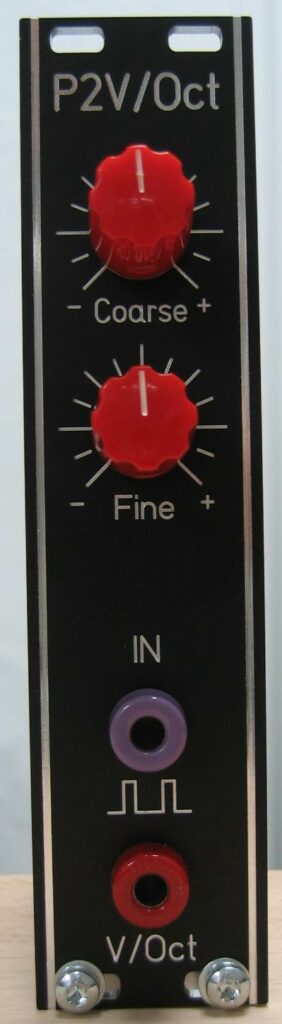
- V/Oct output
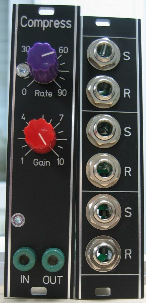
- Offset CV Fine and coarse adjustment
- Runs on +/-15V and +/-12V
- Power consumption around 45mA positive rail, 15mA negative rail
The documentation and the Gerber files for download can be found in my website.
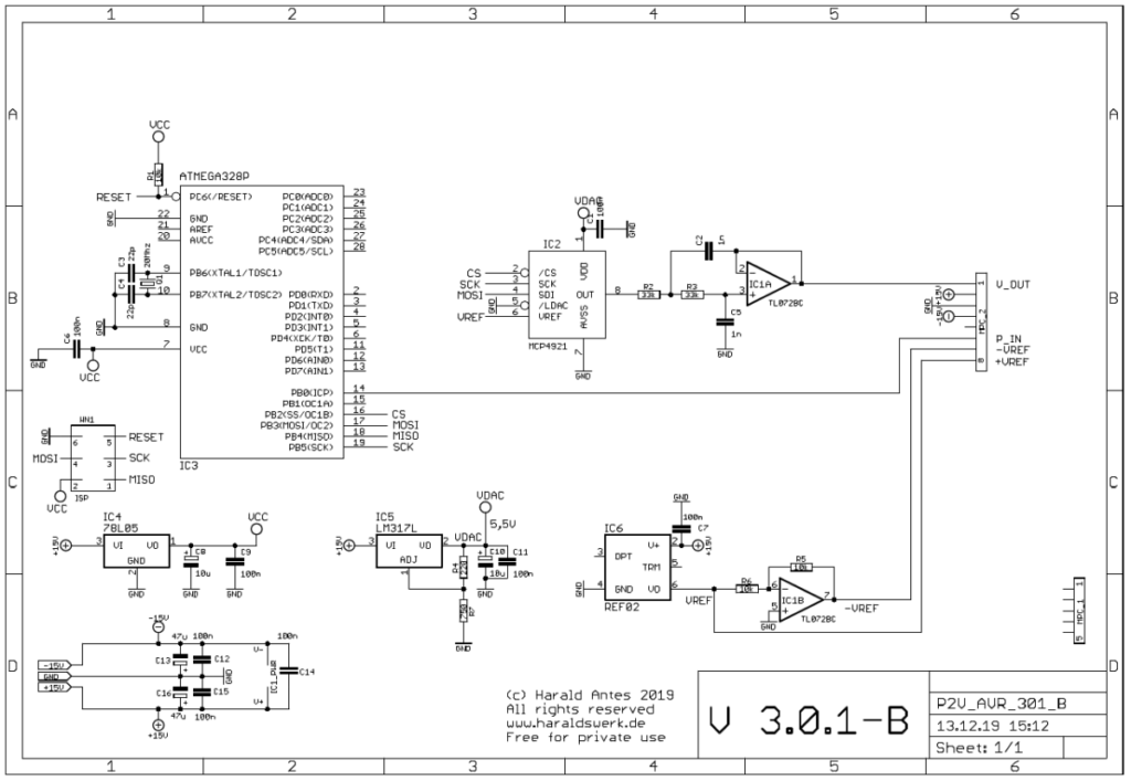
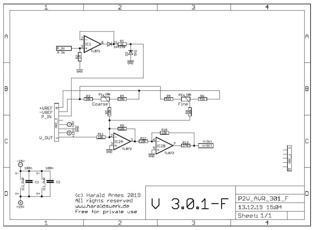
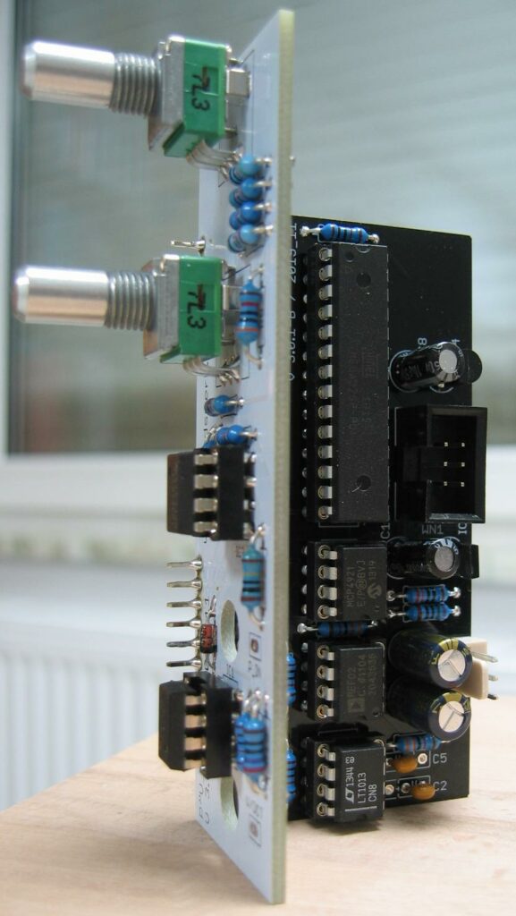
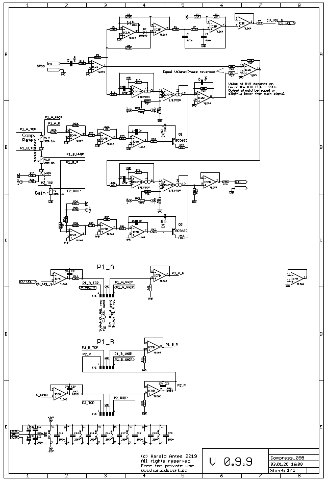
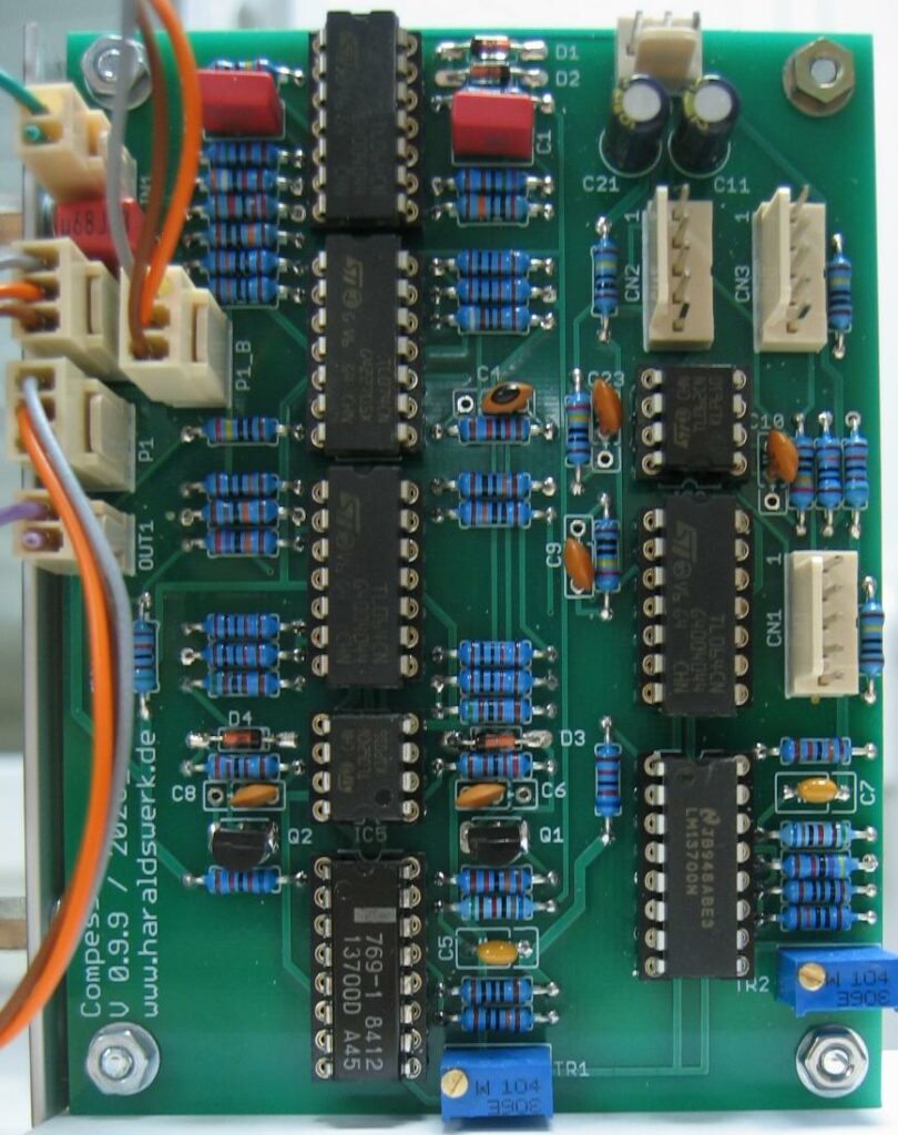
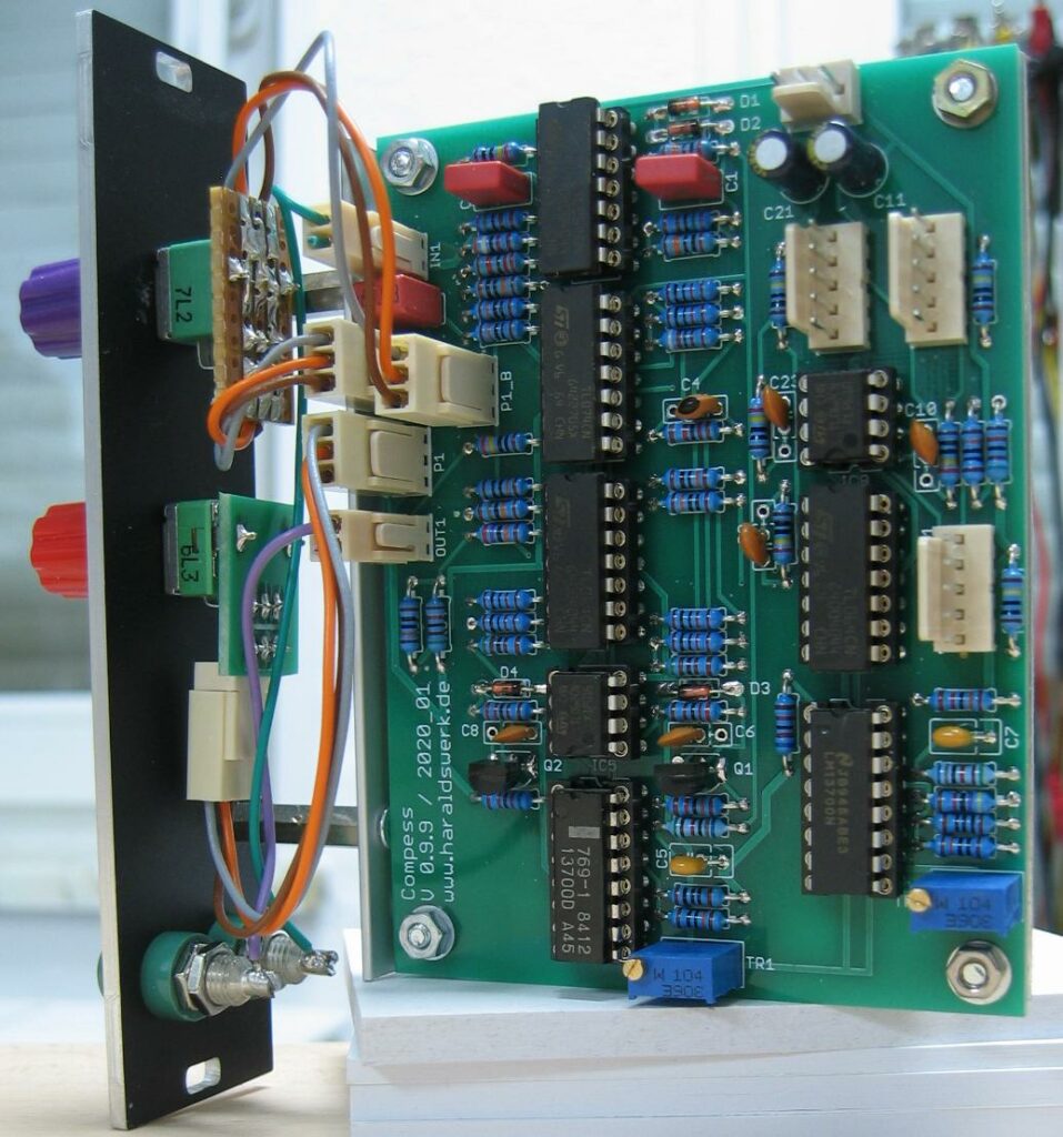
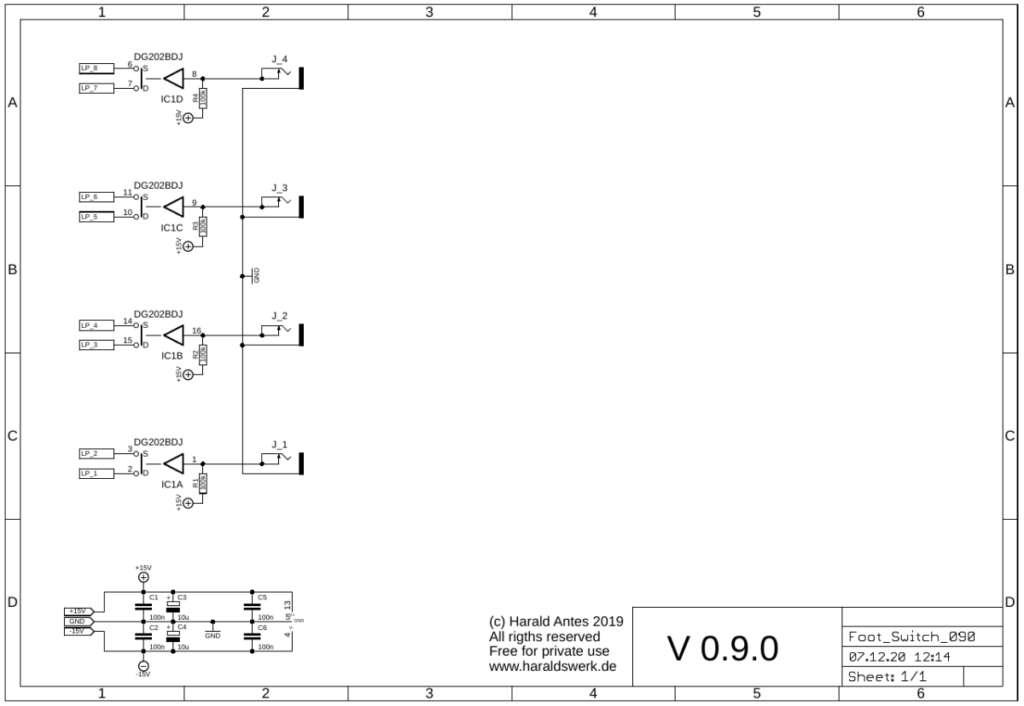
The incoming pulse train is feed to the microprocessor. IC1 (301-F) prevents the microprocessor from negative inputs. Zener D2 prevents from overvoltage. The trigger starts an internal timer of the microprocessor in input capture interrupt mode. The ticks are counted and the count is then looked up in a table. The lookup table provides the values for the V/Oct conversion. The read value is the send to the DAC MCP4921 which is follwed by a low pass (IC1A, 301-B)). IC2A (301-F) adds the offset voltage and IC2B (301-F) corrects the phase.