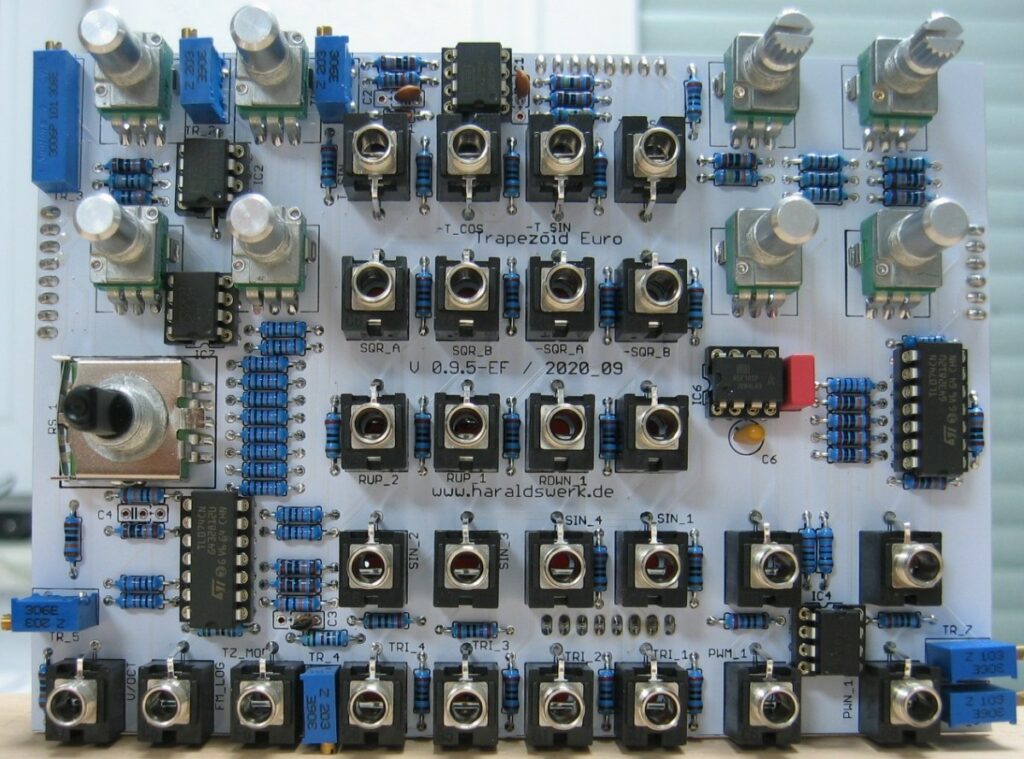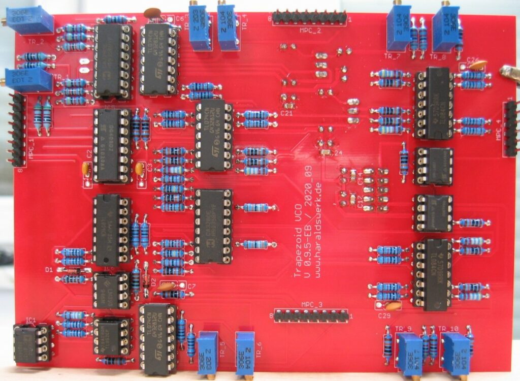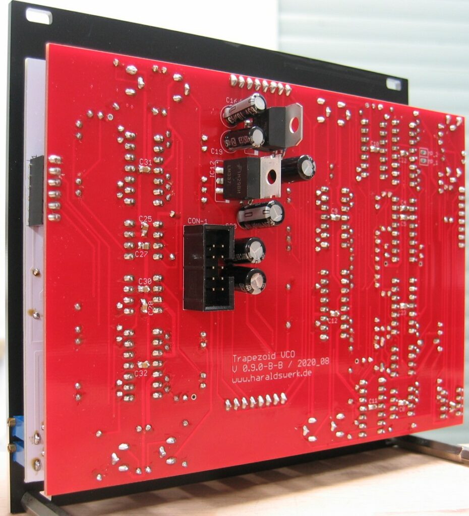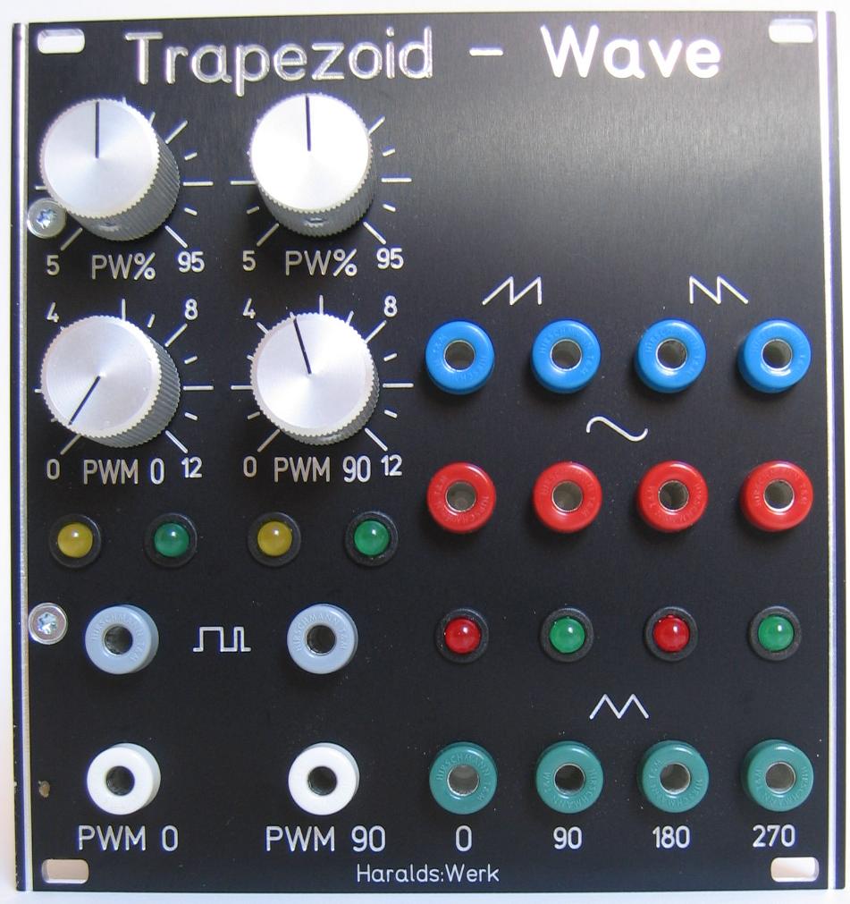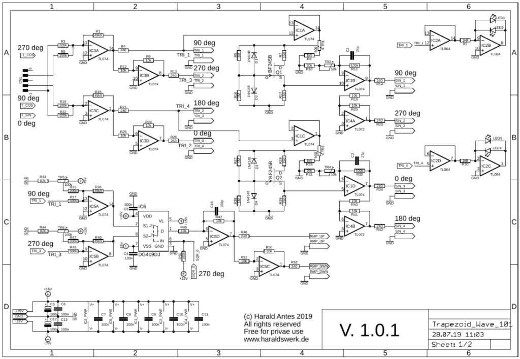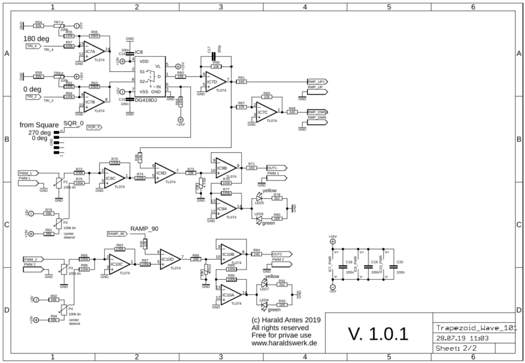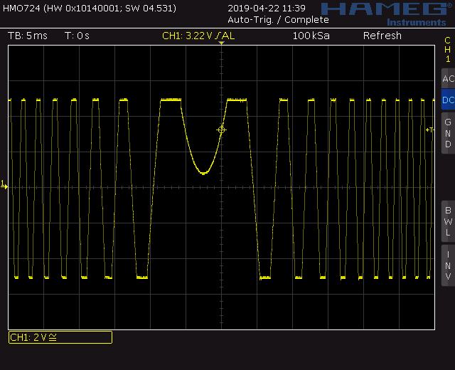
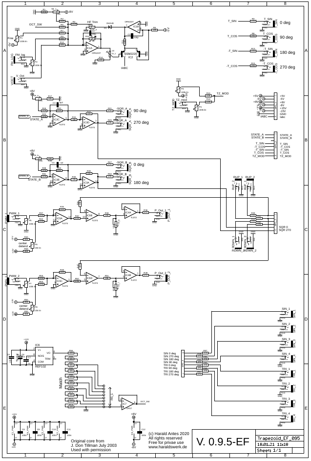
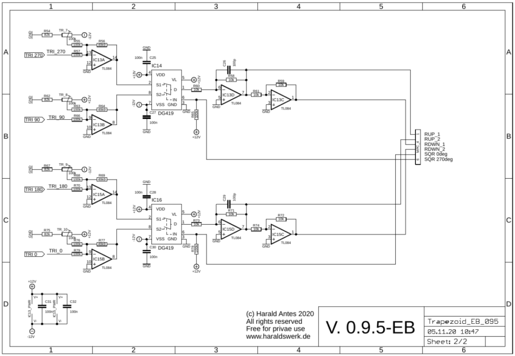
This is my third take on the Trapezoid VCO core designed by Don Tillman. My first implementation for a 15V banana system with separate waveshaper can be found here. My second implementation for a 15V banana system with integrated waveshaper can be found here.This time I moved on to the 12V Eurorack format. The core is still based on the original design from Don (used with permission). I found the original article and schematic about the Trapezoid VCO on Don Tillman’s site (Link to original article from 19 July 2003). The article consists off three parts with the core implementation in part 2. I kept the basic idea and changed nearly everything else. I use an other exponentiator scheme and temperature stabilization. Another reference voltage device is used. A octave switch is added. And quadrature square outputs are implemented. As well as the additional waveforms triangle, sine, ramp up, ramp down and pulse.
Specs and features
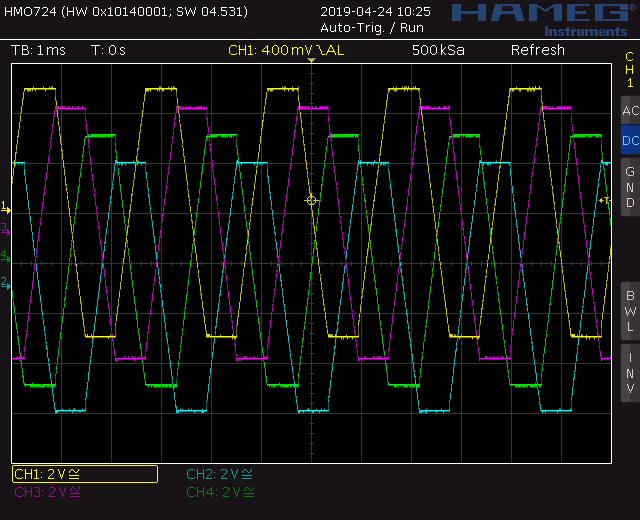
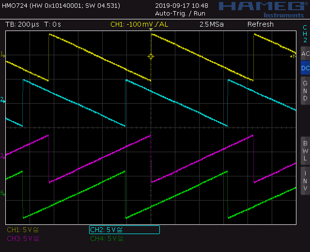
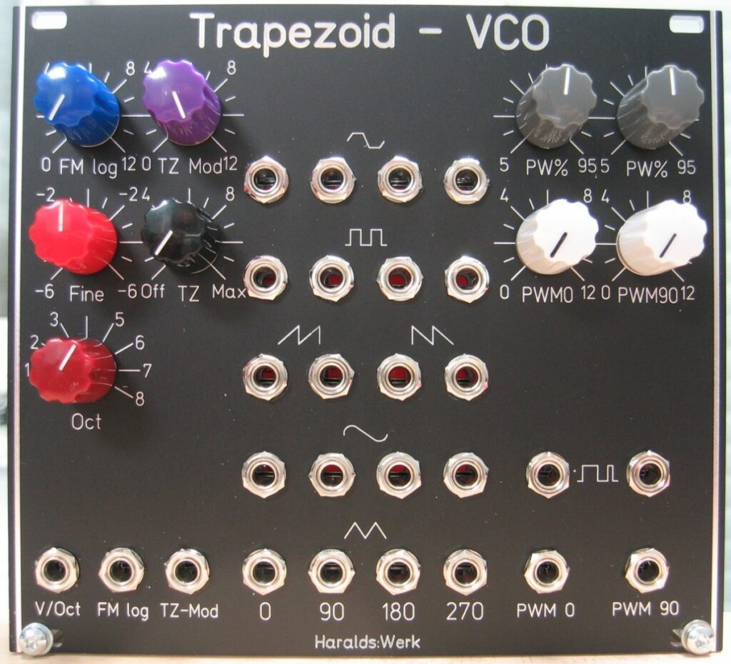
- Trapezoid quadrature output
- Square quadrature output
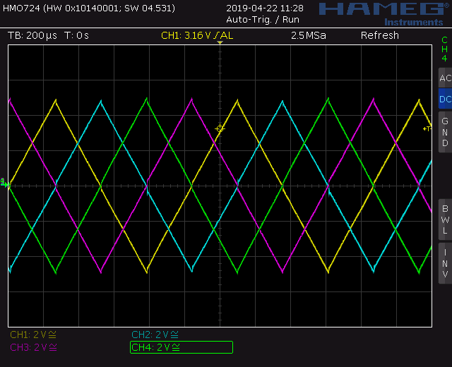
- Triangle quadrature output
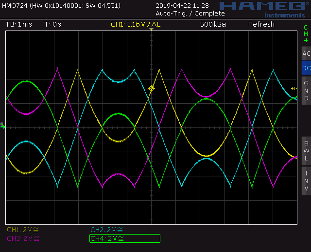
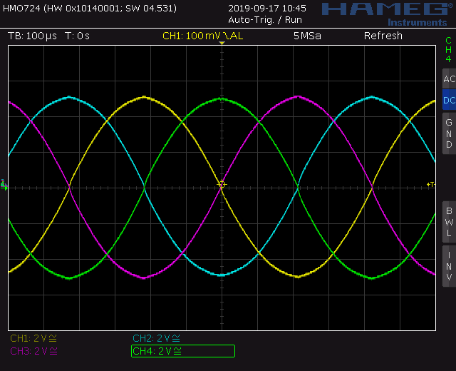
- Sine quadrature output
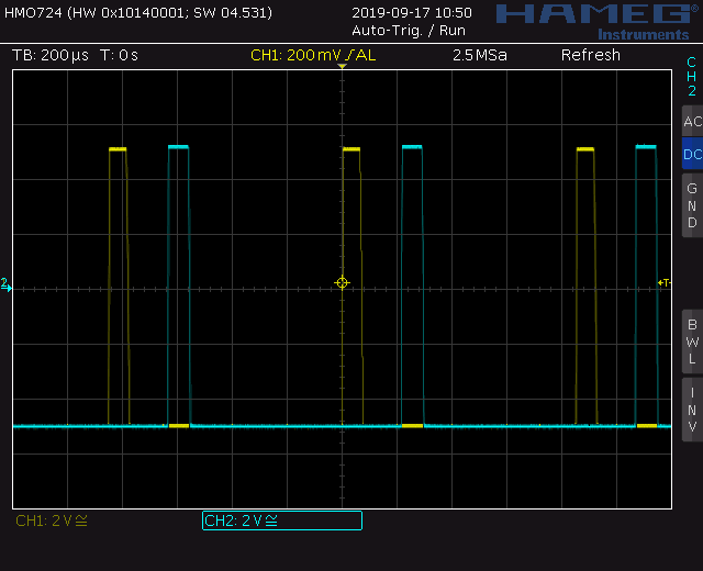
- Pulse output, 0deg, 90deg
- Ramp up output 0deg, 90deg
- Ramp down output 0deg, 90deg
- Octave switch
- Through zero modulation
- PWM input
- V/Oct, FM log and trough zero CV input
- Temperature compensated
- Fine frequency setting
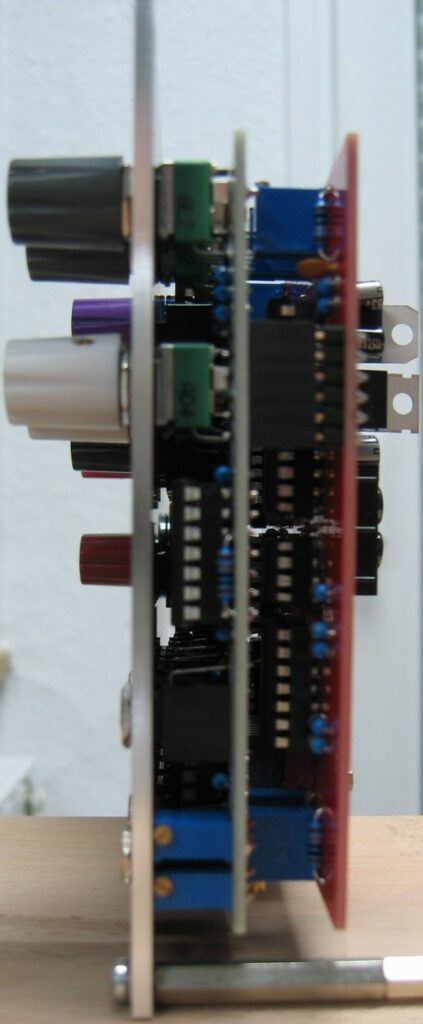
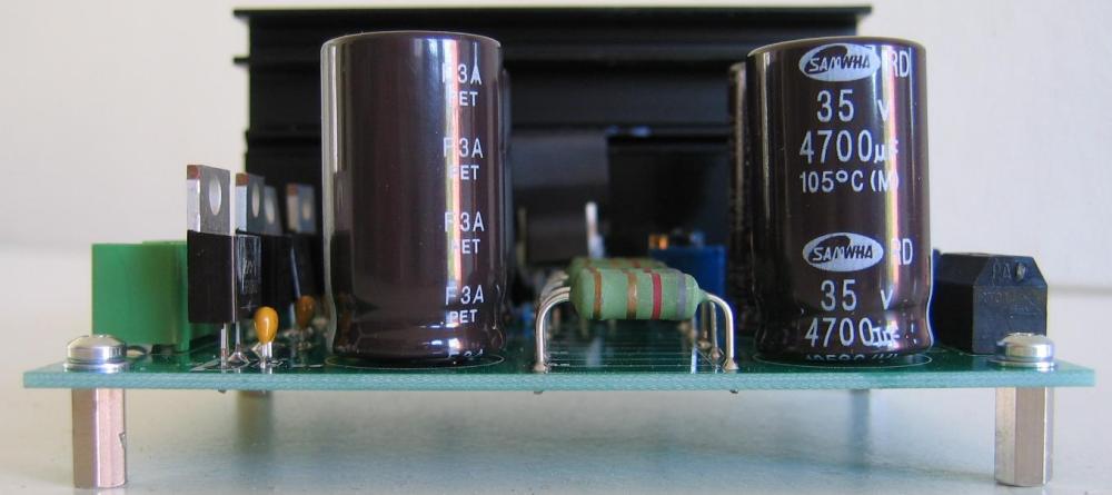
- Runs on +/-15V and +/-12V
- Power consumption around 110mA each rail
The documentation and the Gerber files for download (link) can be found in my website (link).
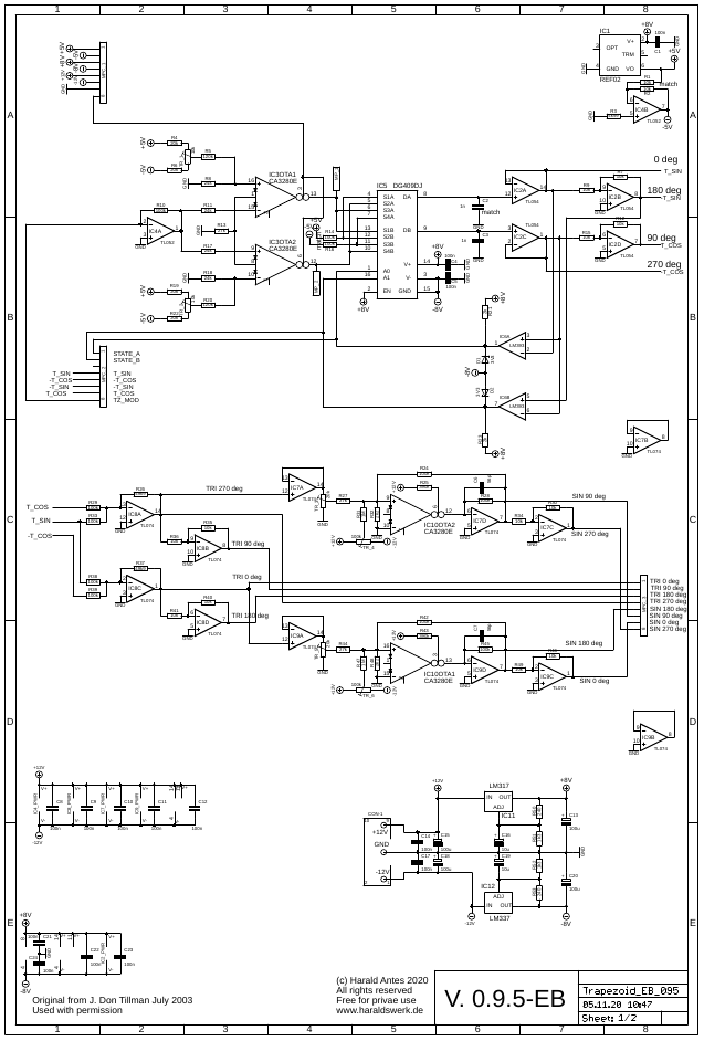
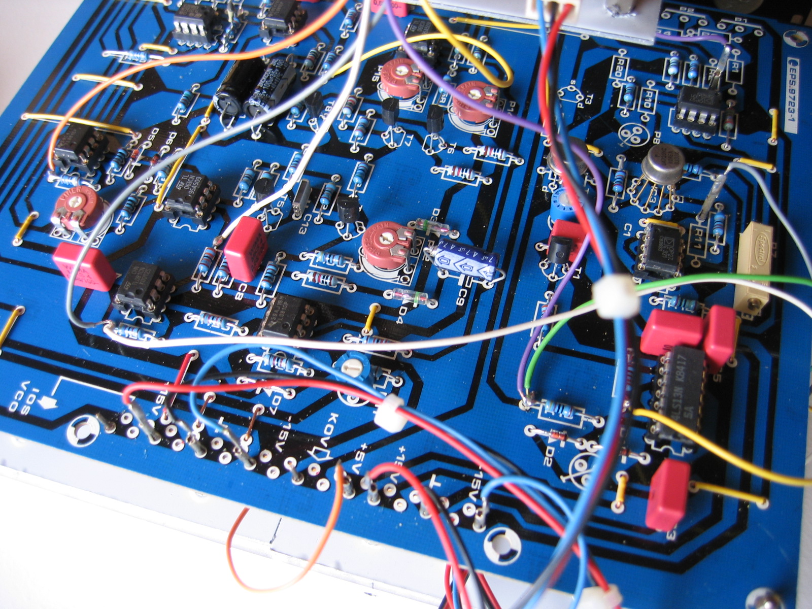
J. Donald Tillman did an excellent job describing the core of his Trapezoid VCO. Please refer to the original article as linked above. Don Tillman gave me the advice to use only two capacitors in the core. The exponentiator I use is a well known and a classical design. You can find many description of it out there. The rest is straight forward.