A short description on how the signal to trigger converter works. The incoming signals are summed up. Every time when the summed signal changes polarity (moving through zero) a trigger is generated. Moving from plus to minus generates a trigger at the negative trigger output, moving from minus to plus generates a trigger at the positive trigger output. Trigger length is about 1.2msec. The gate output stay high as long as the summed input signal stays positive. Trigger and gate voltage is +5V.

Signal to Trigger Converter schematic
The input signals are summed up: Uin1 + Uin2 – Uin3 – Uthreshold. If the sum is above zero volts the output of the comparator IC1A went low. C7 is charged and differentiates the signal. R10 and R13 builds a voltage divider which feeds the comparator IC2C. D4 clamps the negative pulse to ground. This is needed to make sure that the next positive charging pulse starts from zero load in the capacitor. Otherwise the output trigger length will vary with input frequency. R10 and R13 build the unload path for C7. C7, R10 and R13 determines the output trigger length. The comparator IC2C went high when the positive input reaches 7.5V. The output voltage is divided down by R14 and R15. D5 blocks the negative voltage when the comparator switches back to the negative rail. R16 scales the remaining voltage to 5V. IC2D serves as an output buffer. R17 protects the output against shorting to ground. The other path when the summed input signal moves from positive to negative works accordingly.
IC1B scales the output voltage for the gate output to 5V. The output stays at +5V as long as the input comparator stay negative. This means the summed input signal is positive because the comparator inverts the signal.
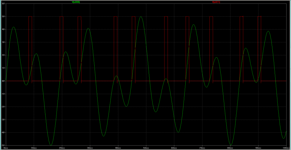
Summed input signal with positive trigger output