Scanning Keyboard: Mechanics – II

Now I have a lot Kimber Allen contacts to clean from clue.

Kimber Allen Gold Wire Contacts

Kimber Allen Gold Wire Contacts

The old glue is hard and it is only removable mechanically. I have to use a small milling machine and magnifying glasses.

Kimber Allen Gold Wire Contact

Kimber Allen Gold Wire Contact

Milling the glue

Milling the glue

First test with a prototype of the bottom side of the new holder.

Contact holder bottom

Contact holder bottom

Contact holder bottom 1 Octave

Contact holder bottom 1 Octave

Contact holder bottom detail

Contact holder bottom detail

Scanning Keyboard: Mechanics – I

For building my polyphonic scanning keyboard I salvaged an old original Elektor Formant 3 octave keyboard. It has 49 keys with Kimber Allen gold wire contacts. The contacts were glued underneath the keys on the metall with some insulation between. Everything needs to be removed. The electronic and the mechanics.

Original Elektor Formant Keyboard

Original Elektor Formant Keyboard

Detail: Original Elektor Formant Keyboard

Detail: Original Elektor Formant Keyboard

Detail: Original Elektor Formant Keyboard, Contacts

Detail: Original Elektor Formant Keyboard, Contacts

Detail: Original Elektor Formant

Detail: Original Elektor Formant

The hard thing was to remove the old glue. It was only possible to do it mechanically with a chisel and a heat gun. And patience.

Elektor Formant keyboard . Removing old glue

Elektor Formant keyboard . Removing old glue

Elektor Formant keyboard . Almost done.

Elektor Formant keyboard . Almost done.

The backside of the raw keyboard is now ready for the new holder.

Keyboard Backside cleaned from glue.

Keyboard Backside cleaned from glue.

The contacts must still be freed from the glue.

Kimber Allen Gold Wire Contacts

Kimber Allen Gold Wire Contacts

Waveshaper: Saw to spaced, square and pulse

For wave shaping from saw to spaced saw I kept the original circuitry from the Elektor Formant. I only have to change some part values due to the different signal level.


Waveshaper: Saw to spaced saw

Waveshaper: Saw to spaced saw

New added is the saw to square waveshaper because I found it usefull to have a symmetrical square output.

Waveshaper: Saw to Square

Waveshaper: Saw to Square

The saw to pulse shaping is quite different to the original but quite standard.

Waveshaper: Saw to Pulse

Waveshaper: Saw to Pulse

Oscilloscope screenshots:

Screenshot: Saw to square and spaced saw

Screenshot: Saw to square and spaced saw

Screenshot: Saw to pulse

Screenshot: Saw to pulse

Waveshaper: Start

As said before i loosely follow the Elektor Formant path with my circuitry. So I did with the waveshaper for my Next Generation Formant, NGF. It will have 10Vpp saw input from my NGF VCO and saw, spaced saw, triangle, sine, square and pulse output, all 10Vpp. This follows the original. I only added the square output.

Waveshaper Block Diagram

Waveshaper Block Diagram

I changed some of the circuitry for better performance, particularly the saw to triangle and triangle to sine part. And did a lot of breadboarding.

Waveshaper Breadboarding

Waveshaper Breadboarding

Building and testing the prototype on stripboard.

Waveshaper prototyping

Waveshaper prototyping

NGF VCO Core one (part three)

The PCB for the NGF VCO Core one (based on the Elektor Formant) with the corrected footprint for the uA726 finally arrived this week. I stuffed the PCB and wired them up to the front panels.

NGF VCO Core one (Elektor Formant based)

NGF VCO Core one (Elektor Formant based)

They worked as expected. No faults. No problems. I only made some minor changes for the next PCB run. I added a trim-pot to make the output voltage adjustable and put a 5p6F capacitor in parallel to the feedback resistor of the output OpAmp.

NGF VCO Core one PCB

NGF VCO Core one PCB

You can see my “wind shield” on the left and the added small capacitor on the low right site. For measuring the temperature for the uA726 it is a must to use heat transfer paste. Otherwise your figures are way of.

NGF VCO Core one PCB temp measuring

NGF VCO Core one PCB temp measuring

I did this to determine what resistor to use for the heater temperature control. In the datasheet 75kOhms with 15V are used. The Mini Moog used 49k9Ohms with 10V. I decided to use 160kOhm (15V) with a “wind shield” used to avoid airflow around the heated uA726. This keeps the temperature well above room temperature and gives lower thermal stress for the device. Which hopefully makes for a longer life.

Elektor Formant 24dB VCF rebuild (part one)

While waiting for the PCB’s of the Elektor Formant VCO rebuild, NGF VCA DC uno and the Vocoder project, I started the rebuild of the Elektor Formant 24dB VCF. I have already an modified version of the original. Now I want to rebuild the original with easily available parts with better specs and better overall performance. I will add the features of my modified version as well. The features are: Voltage controlled Q, voltage controlled linear slope controll, better ENV controll for the HP with “gender changer”, simple level control. To start with I just put up one 6dB Filter cell on breadboard to verify some part values.

Elektor Formant VCF 6dB filter cell

Elektor Formant VCF 6dB filter cell on breadboard

Four of this cells makes the core of the 24dB Elektor Formant VCF rebuild. You can add two more to go for 36dB as well. Let’s see.

Elektor Formant 24dB VCF 6dB filter cell

Elektor Formant 24dB VCF – 6dB filter cell

NGF VCO Core one (Elektor Formant based) Part two

This week I stuffed the PCB of my Elektor Formant based NGF VCO Core one. Before soldering the precious uA726 in, I checked the footprint on the PCB, because I developed it in Eagle by myself. Lucky me! I screwed it up! I did the connection between pins and pads the other way around. I have to correct this before the next run of boards. To make use of the board anyway for testing I soldered the uA726 from the back and used some wires to connect the pins with the right pads.

20140927_01

I left some resistors out because I wanted to determine their right values while testing. None of them necessary for the basic function. I put the control voltage IC’s REF02 and REF102 in and tested the voltage. Fine. I put the other IC ‘s in, fired it up and the VCO worked as intended. A nice clean saw at the output.

20140927_02

Octave switch worked, fine adjust worked, sync in worked. FM lin, FM log worked with input resistors yet to be determined. Temperature control resistor is set to120k at the moment but should be checked again later. The Elektor Formant uses 200k here, the example in the datasheet of the uA726 says 75k with 15V. The Mini Moog used 49k9 with 10V on the second version VCO. So everything fine? Nope. I forgot that the output peak voltage should be at 5Vpp. I simply forgot the output amp and the output C to eliminate the d.c. offset as well.

The sync output pulse was derived directly from pin 8 of the 74LS13. But because you can sync the VCO with any input wave form I just eliminated this part completely. This gives me the chance retrofitting the 5Vpp output with the now freed OpAmp.

20140927_03

This week left me with a quite good working VCO. The PCB board must be redone but that’s not a big thing.

NGF VCO Core one (Elektor Formant based) Part one

To start with this Blog i want to write about a new PCB project which roots go back to the seventies. At this time a German electronics magazine published an diy analog synthesizer. The Elektor Formant. They sold PCB’s and some third party vendors sold kits as well.

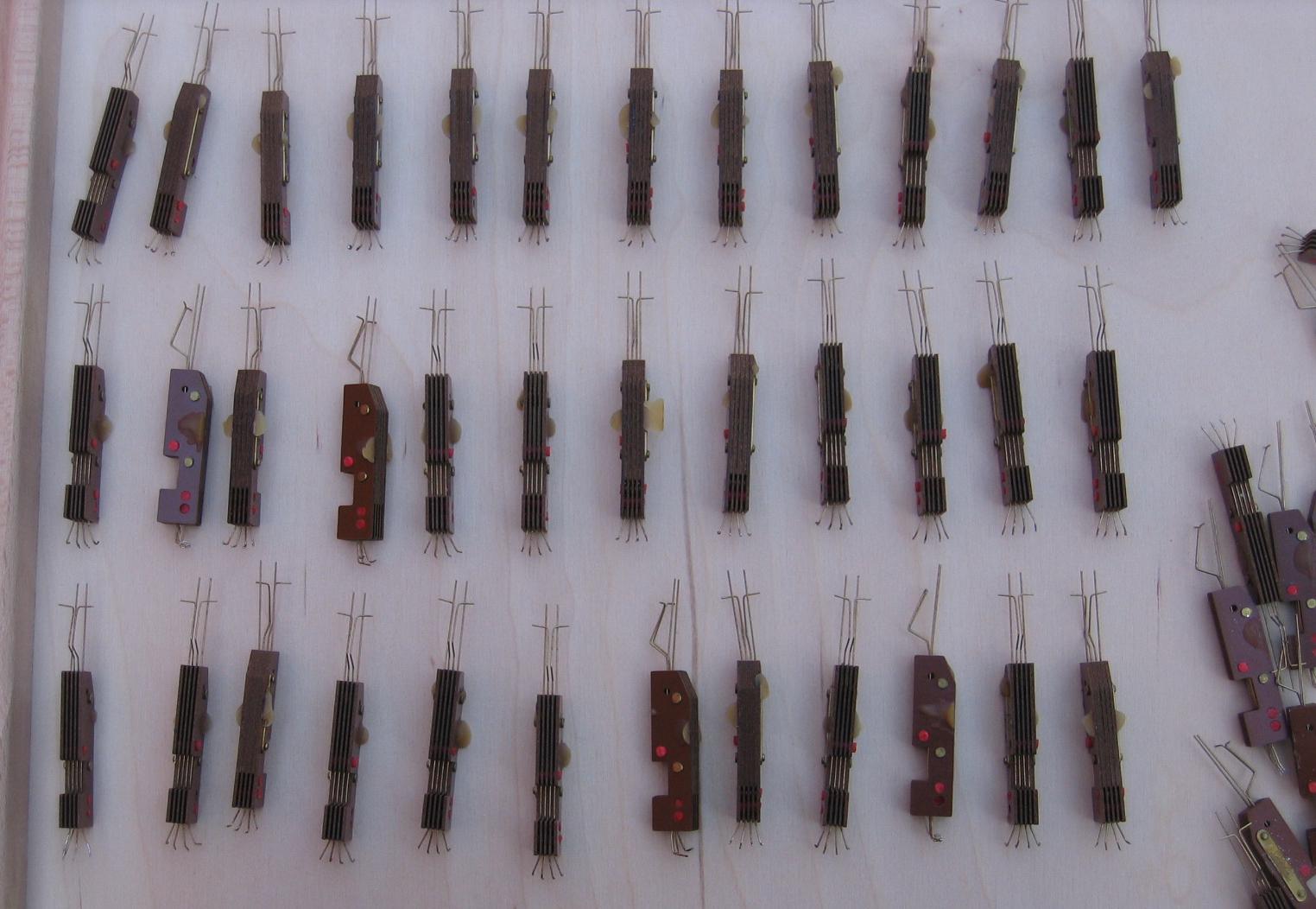
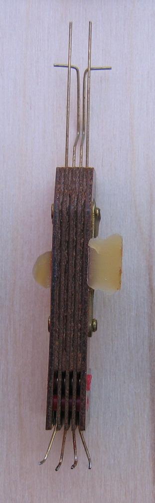
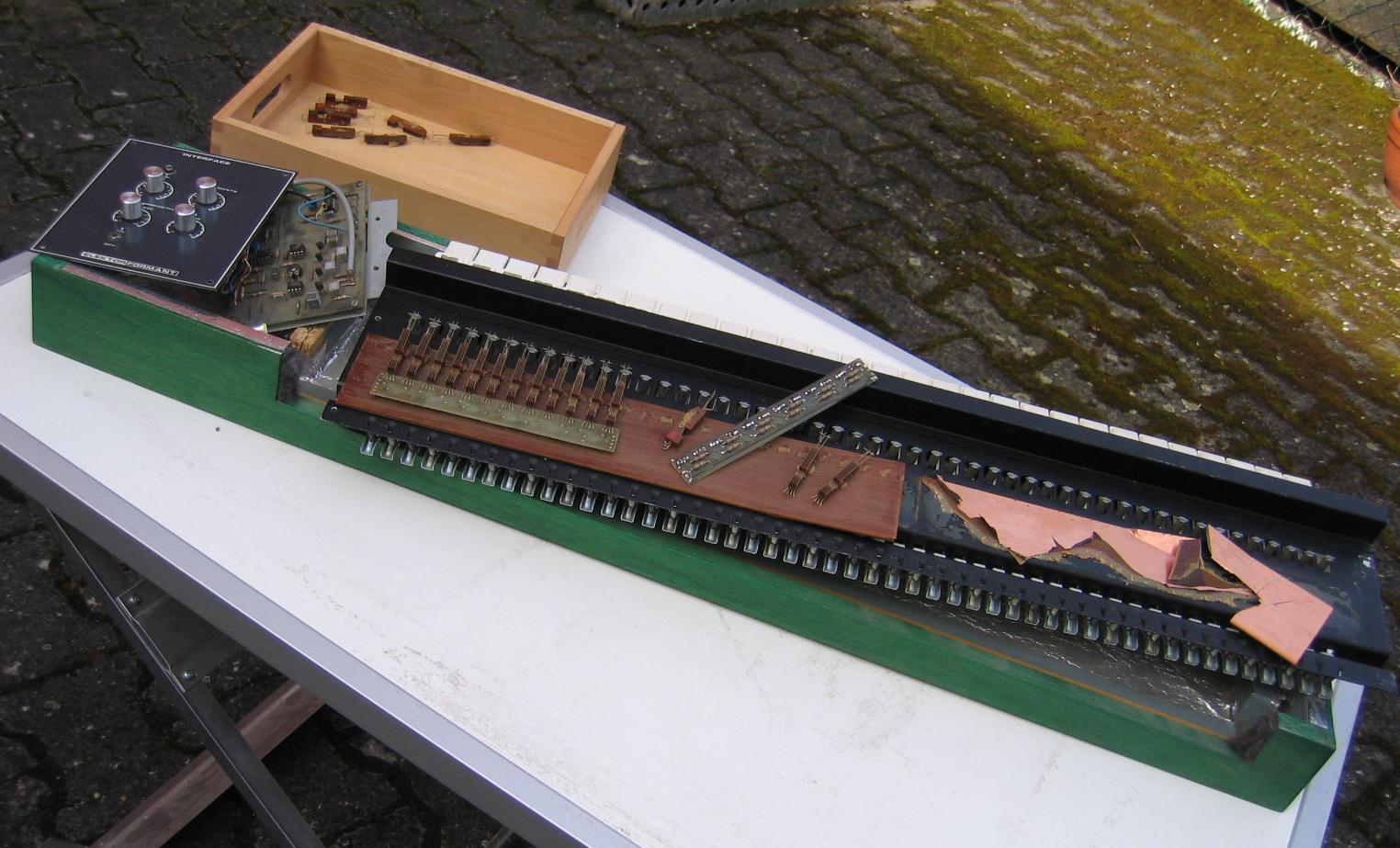
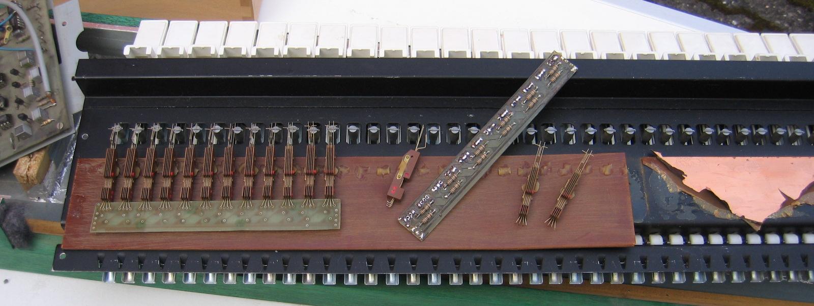
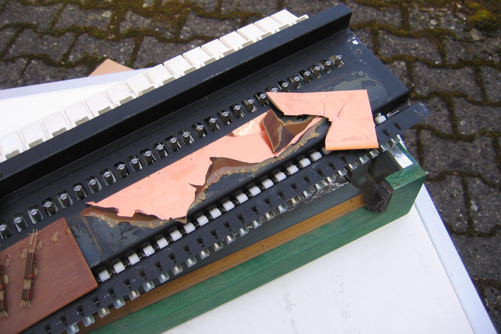
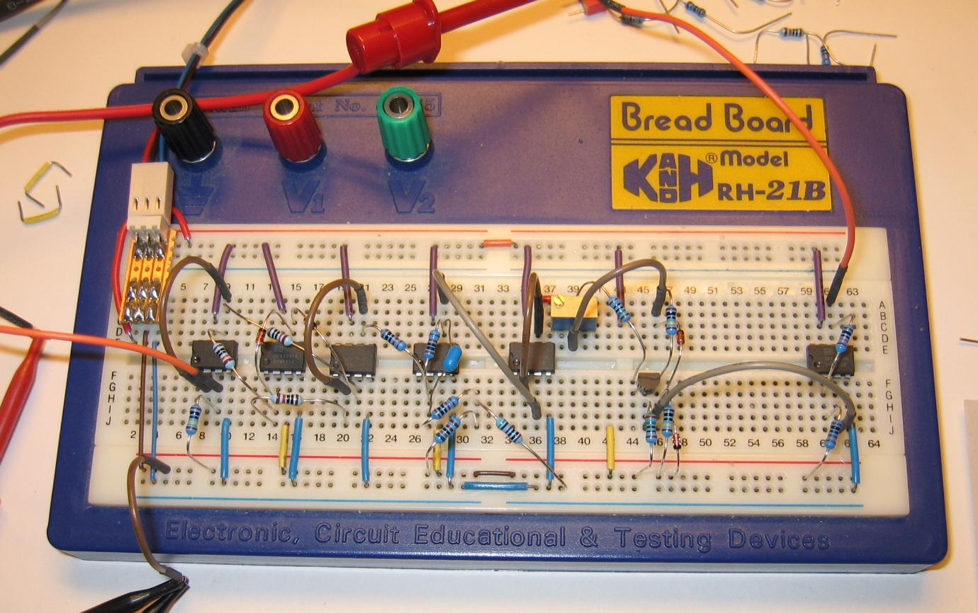
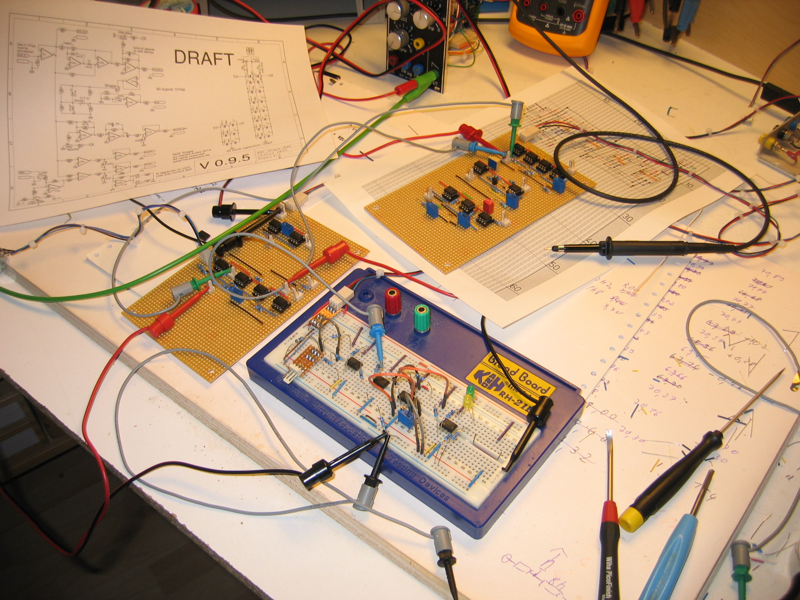
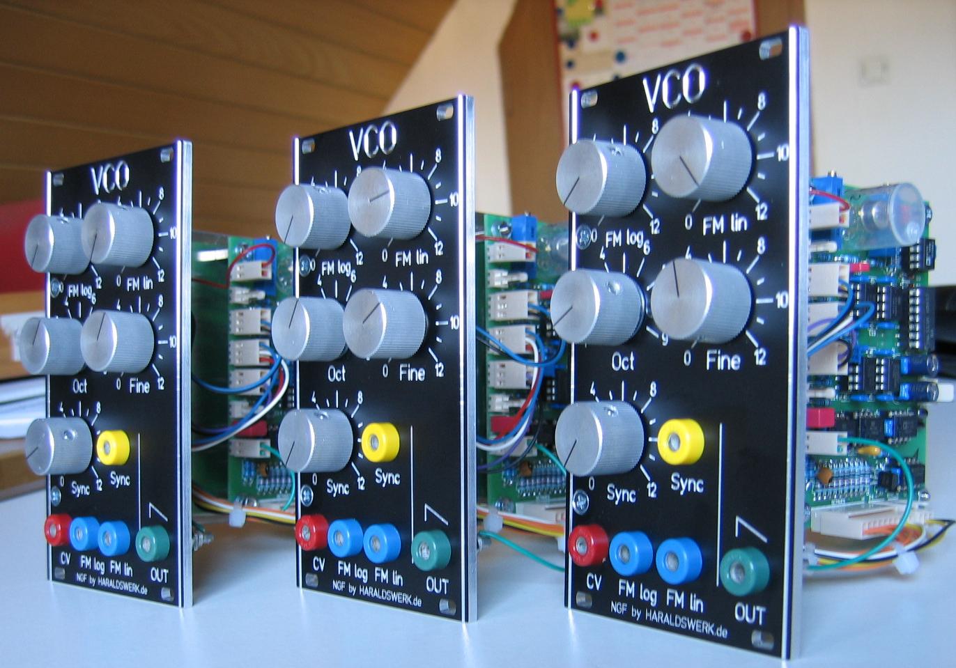
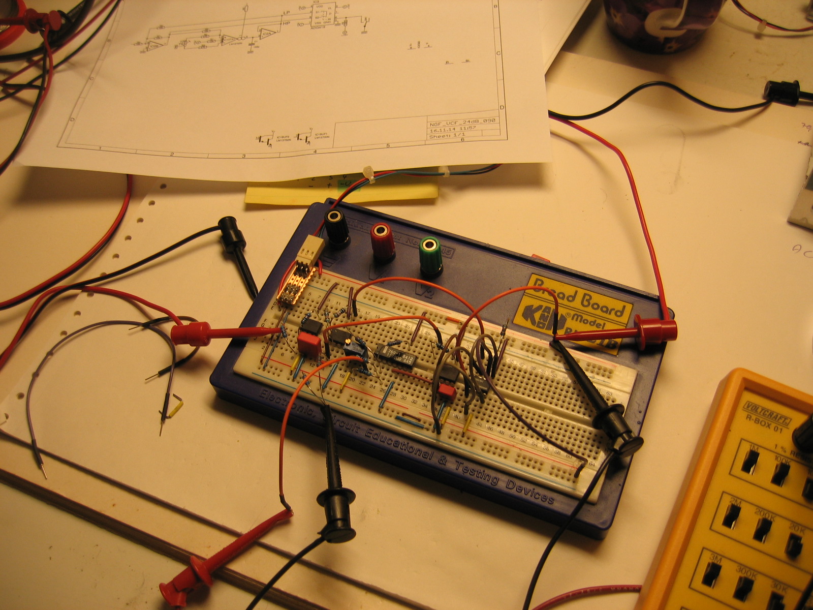
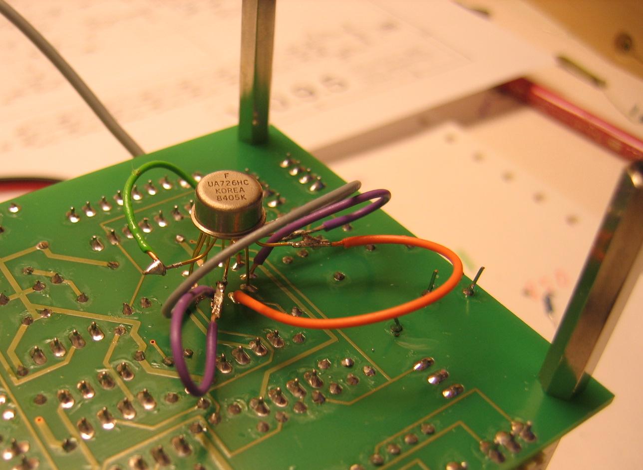
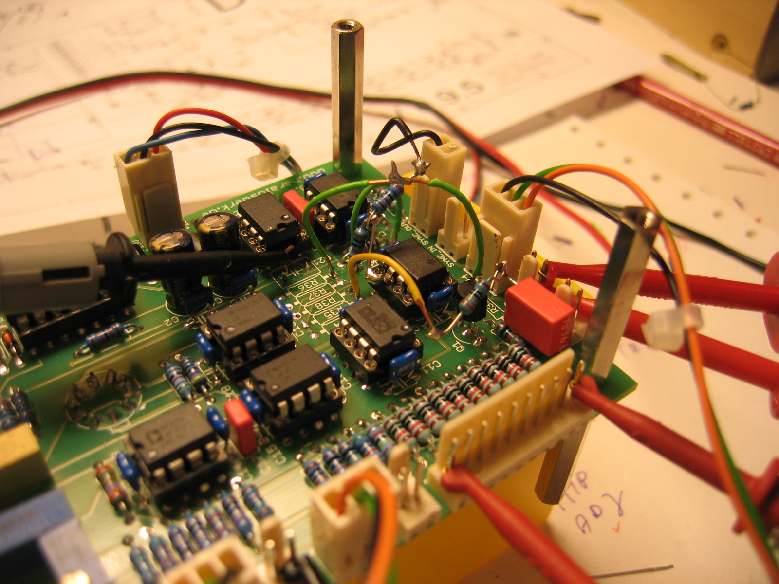
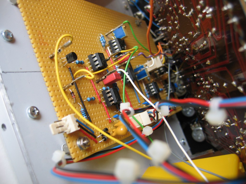
So i bought and build my first few modules of an analog synthesizer. The VCO was build around the Fairchild uA726 temperature controlled differential pair, the same one used in the Mini Moog second oscillator board. Over the years a added some features to the VCO that i found useful. For instance: octave switch, sync in and out, fixed square out, FM lin, voltage reference, output mixer and some more. Getting rid of the 5V PSU was a big step. I made the changes recommended in the second Formant book as well. This leads to some wiring …

IMG_3639
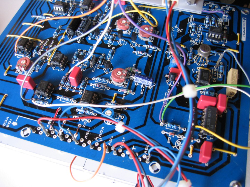
and an additional stripboard.

IMG_3638

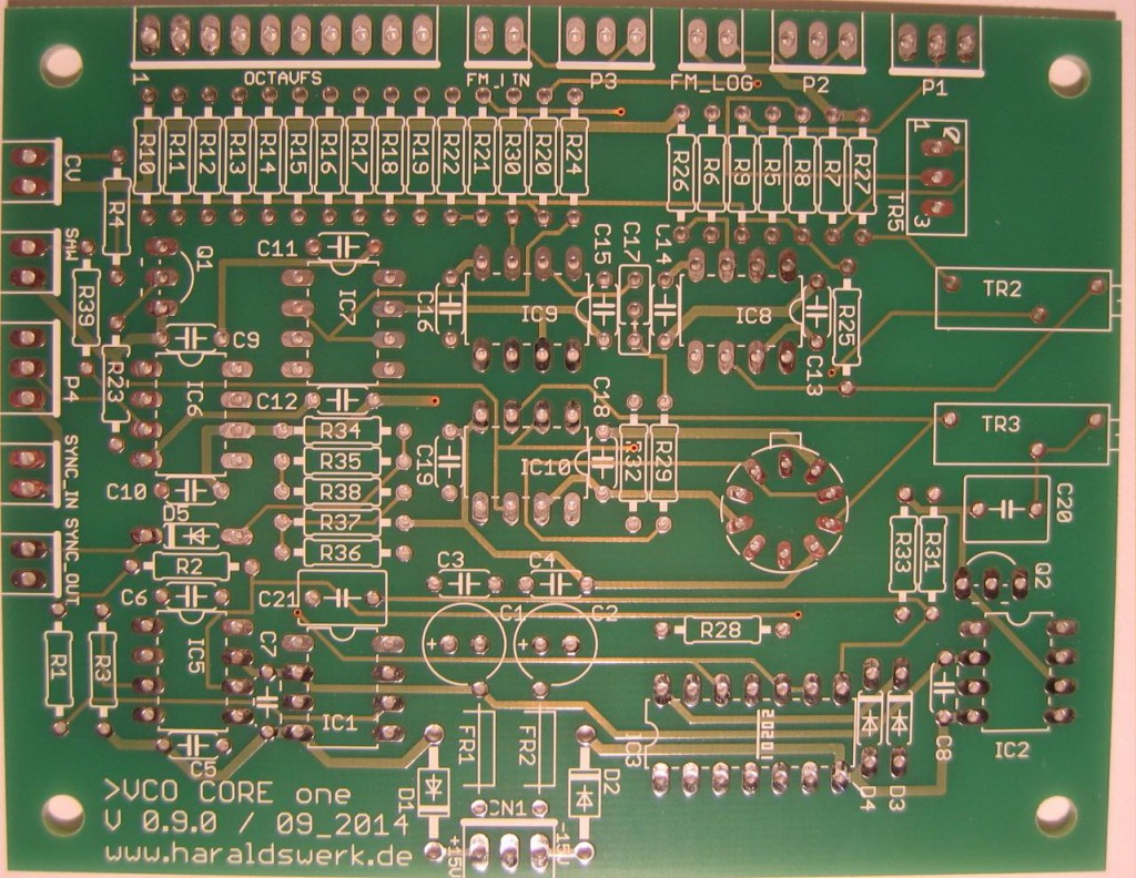
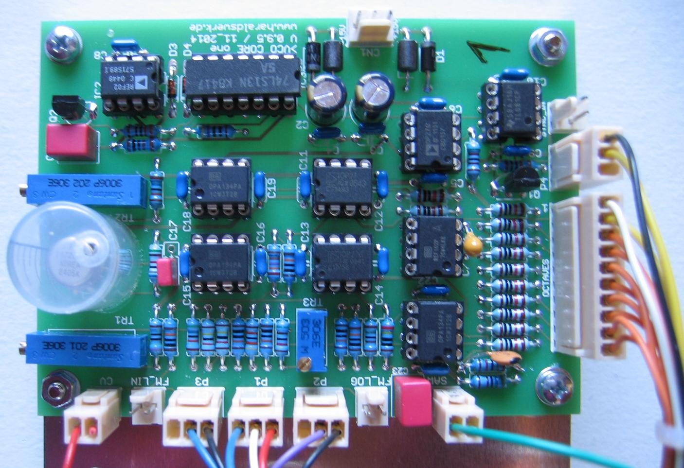
So i decided to consolidate what i have done and put all those changes on one PCB. This was possible because i have all the used obsolete parts at hand. If you want to follow this path first make shure that you can get hold on those parts (uA726, 74LS13). They are still available at a price but you have to search for them.

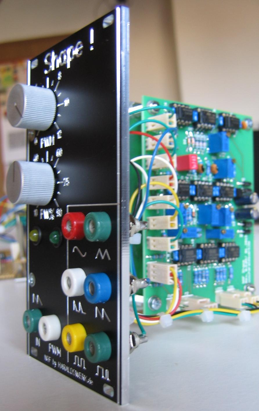
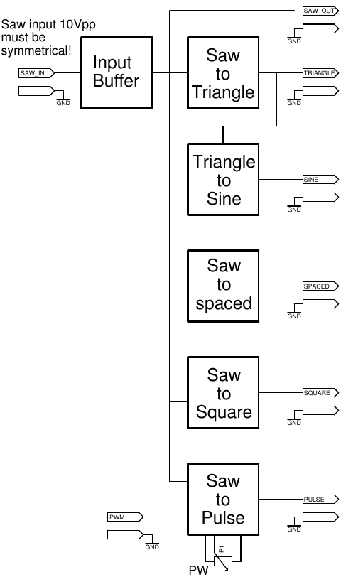
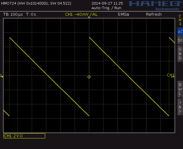
I only did the core VCO here. The wave shaper will be tackled later in a separate project. There are two categories of changes i did. Additions i found usefull to have and changes to increase stability. Usefull additions: Octave switch, FM lin, Sync in, Sync (pulse) out. Increased stability: Stabilized control voltages, getting rid off the 5V power suplly. Details and schematic can be found on my website.

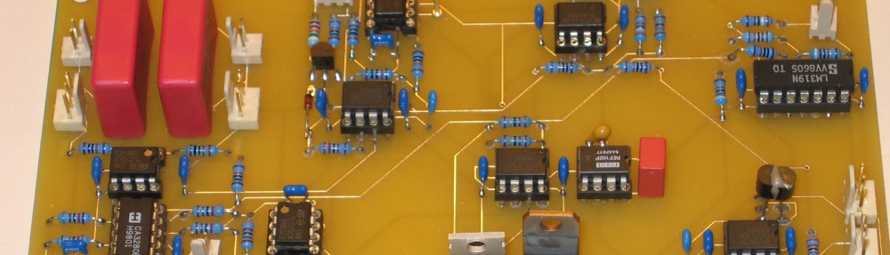
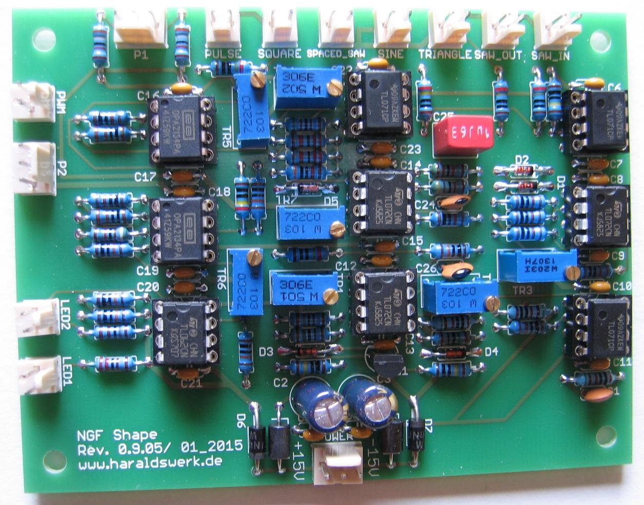
The PCB just arrived. Now time to stuff it.

IMG_3679