Multiple voltage controlled logarithmic current sources are often needed when developing new modules. They are standard building blocks of nearly every VCF and VCA. And useful when the Gm of OTA’s must be checked or matched. So i thought it comes in handy to have just such a current source around as a “module” when needed. I designed a schematic and a small PCB with eight current outputs. It can manually operated with a potentiometer and modulated with an external voltage as well. I added a linear voltage input and a sign changer. The sign changer is very useful when testing a HPF which needed reversed CV voltage to operate properly. The output current is limited with the output resistors. Increasing this resistors lowers the maximum output current. If you already have current limiting resistors in your module under test, you can bypass the build in resistors with jumpers.
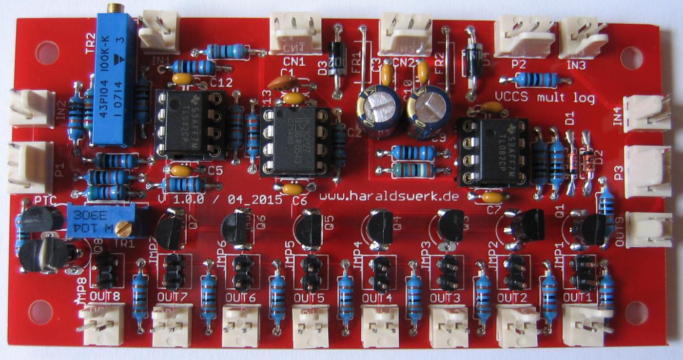
Logarithmic voltage controlled current source
Logarithmic voltage controlled current source
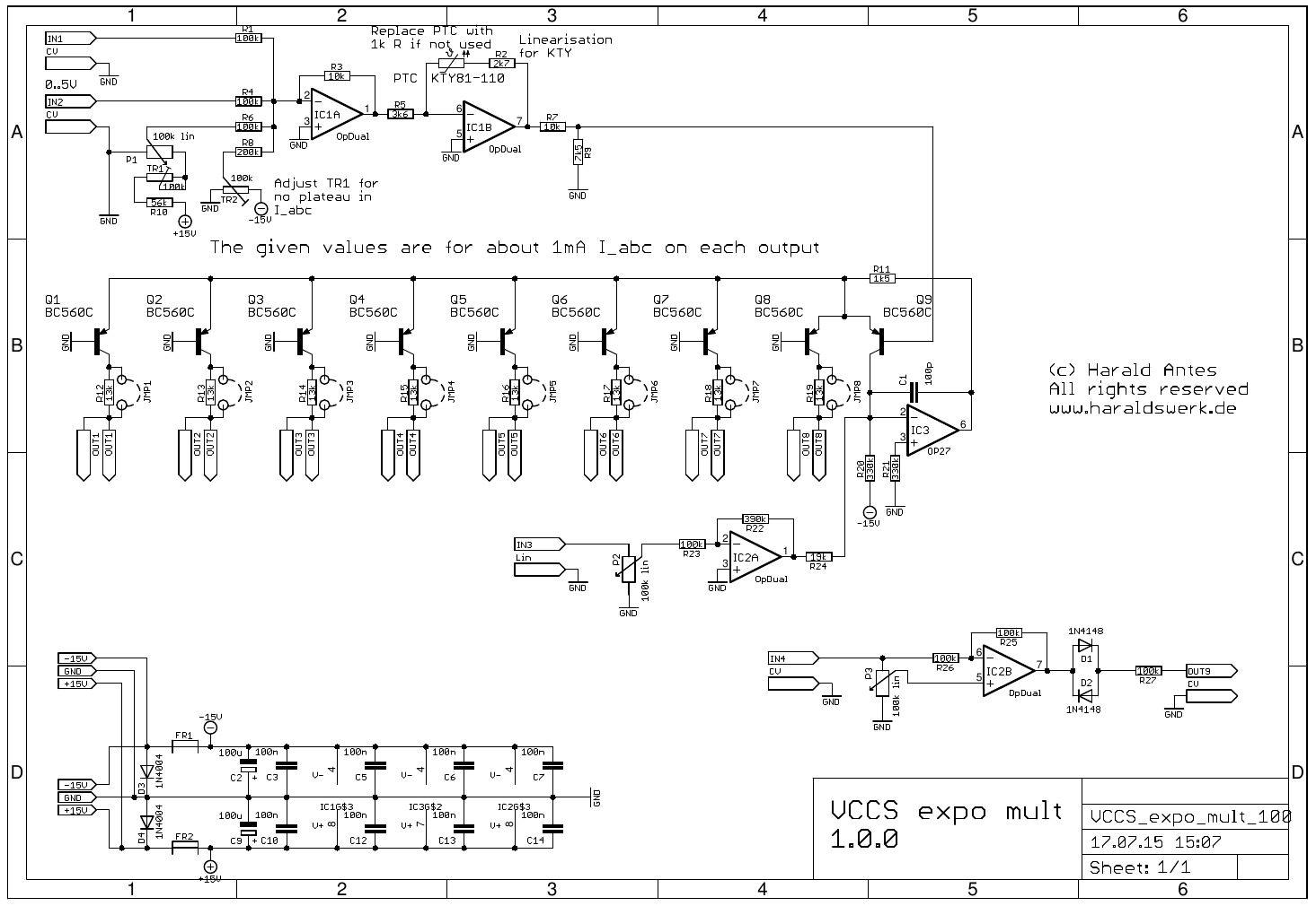
IC1A acts as a voltage adder. IC1B with the KTY81-110 is used for temperature compensation. It can be replaced with a 1k resistor if not needed. R2 is needed for linearizing the KTY81. Q9 Q8 and IC3 builds the exponentiator and current source. Q1 to Q7 are the additional outputs. R12 to R19 limits the maximum current. Increasing their values lowers the maximum current. IC2A serves as linear input. The sign changer is build around IC2B.
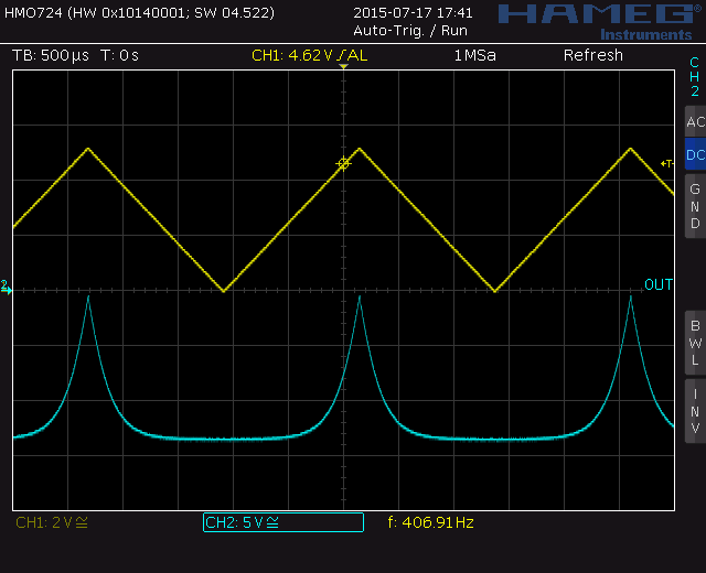
Logarithmic voltage controlled current source. Right calibration.
If you do the calibration correctly you can see a sharp peak at the logarithmic curve. The procedure is described on my website.