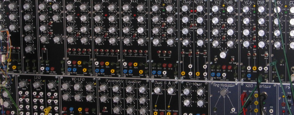
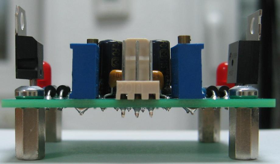
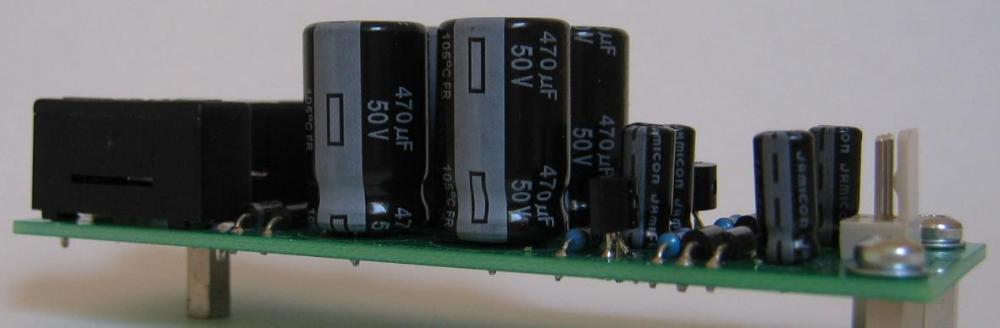
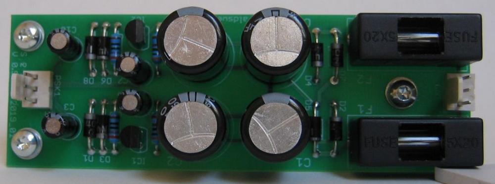
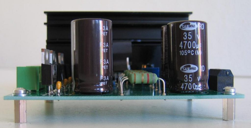
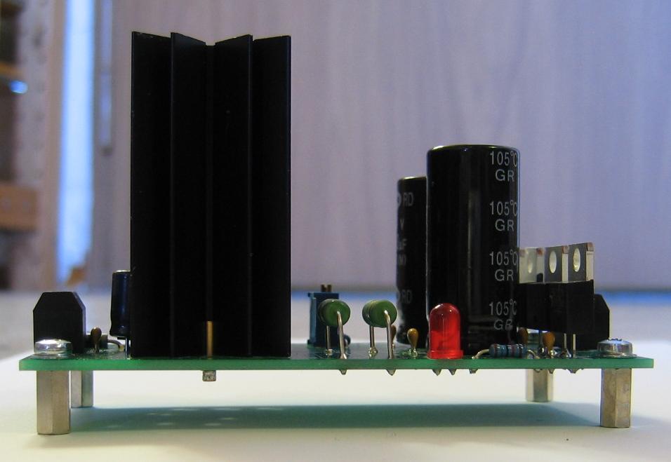
For my Next Generation Formant project i needed a replacement for the obsolete uA726, because i wanted to stay as close as possible to the original Elektor Formant VCO with my NGF VCO Core 2. This means a heated exponential matched transistor pair. There are a variety of possibilities to achieve this goal. Most of those solutions uses now obsolete parts or are hard to build. But there is still on well known solution with with the 3046 transistor array. And best, it is still available. At least the SMD Version is still in production. The DIL version can be found as well, but is no longer in production.
The circuitry I found on the net did only use one transistor for the heating. This leaves one transistor unused. My thought is using two transistors makes for a faster heating up and more stability against environmental change. To my surprise I can not find a solution which uses two transistors instead of one. Here is my take on the circuitry.
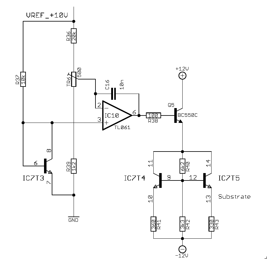
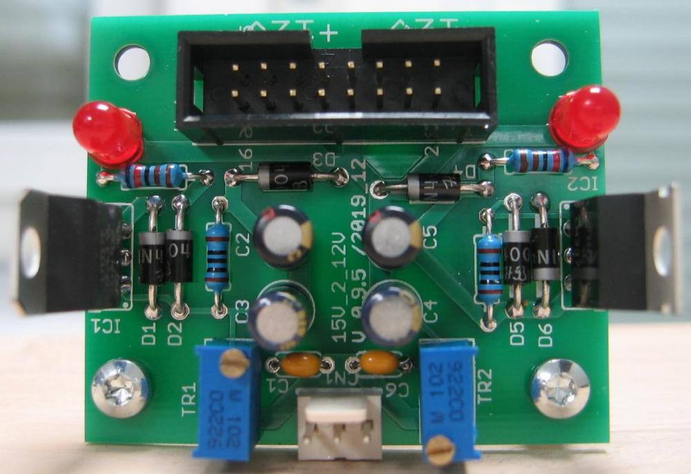
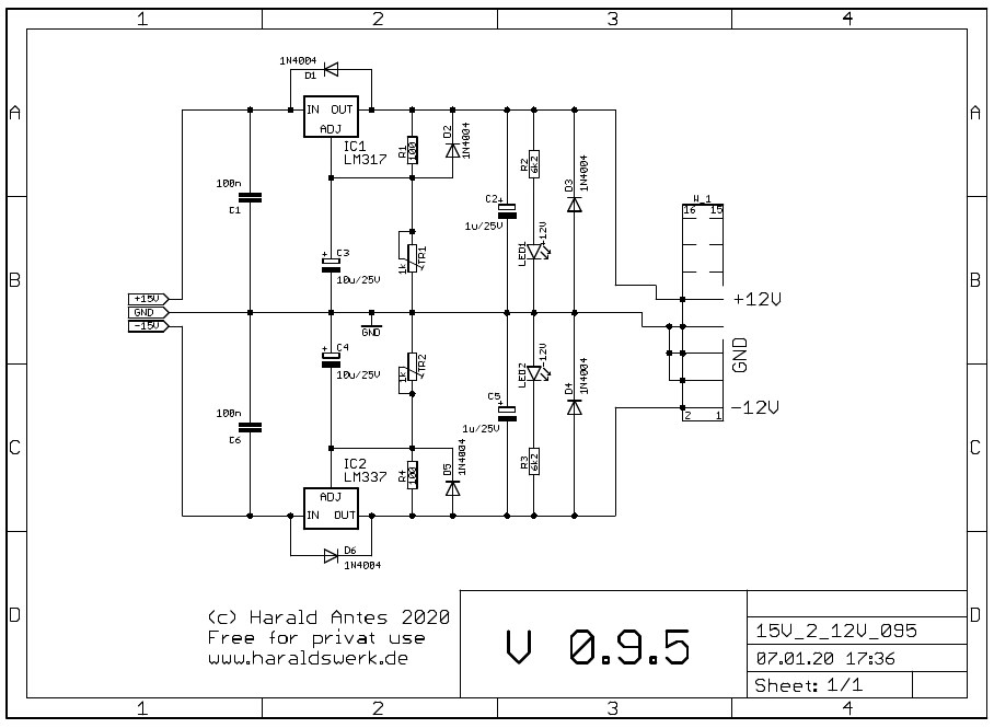
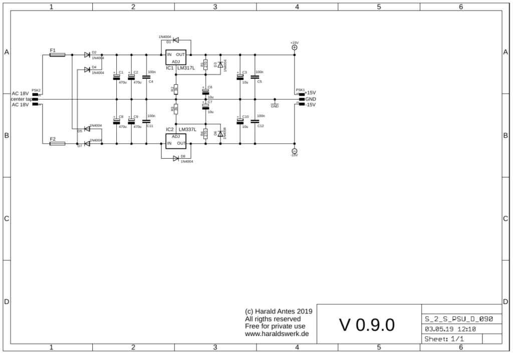
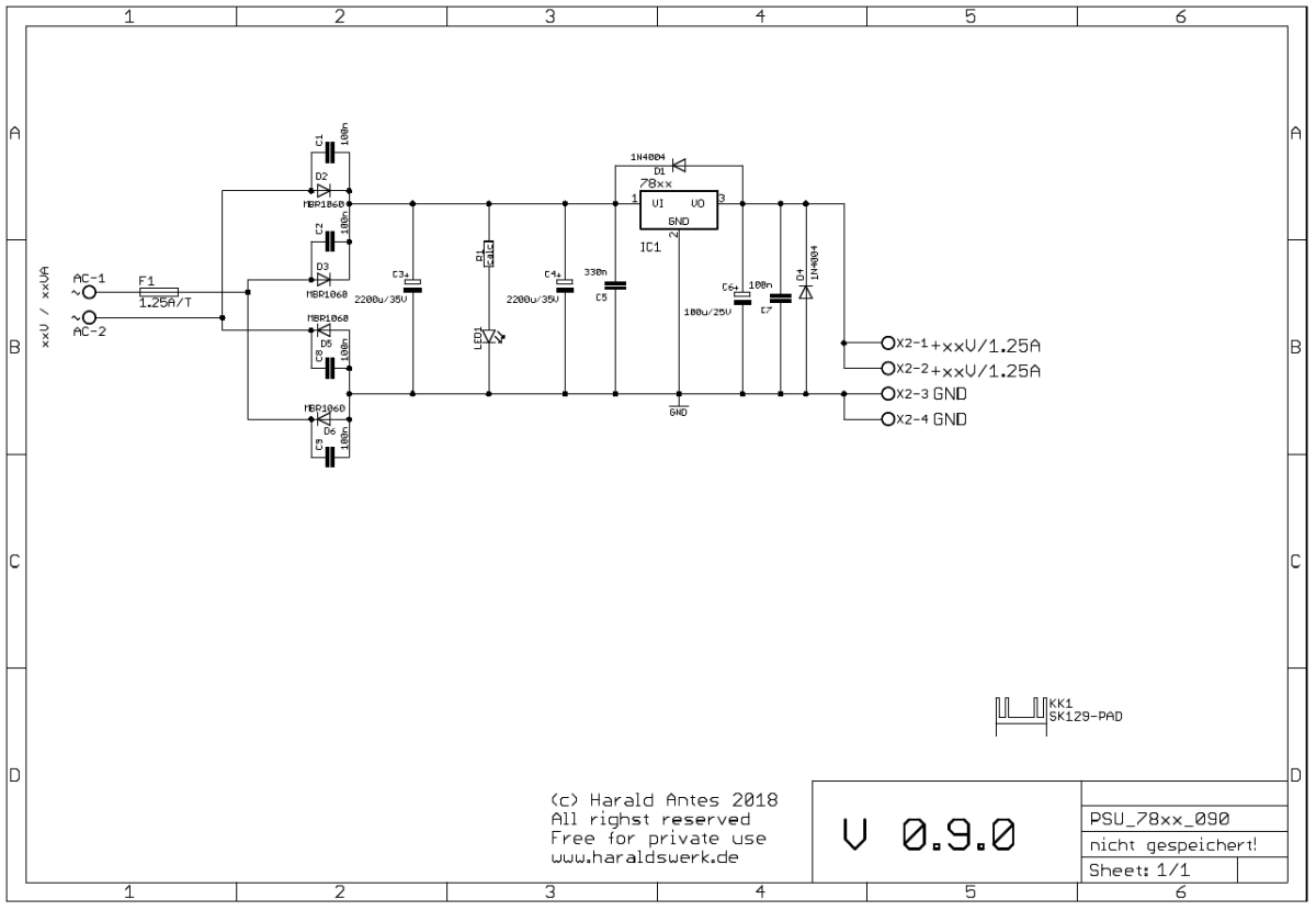
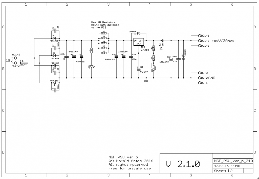
3046 heater schematic
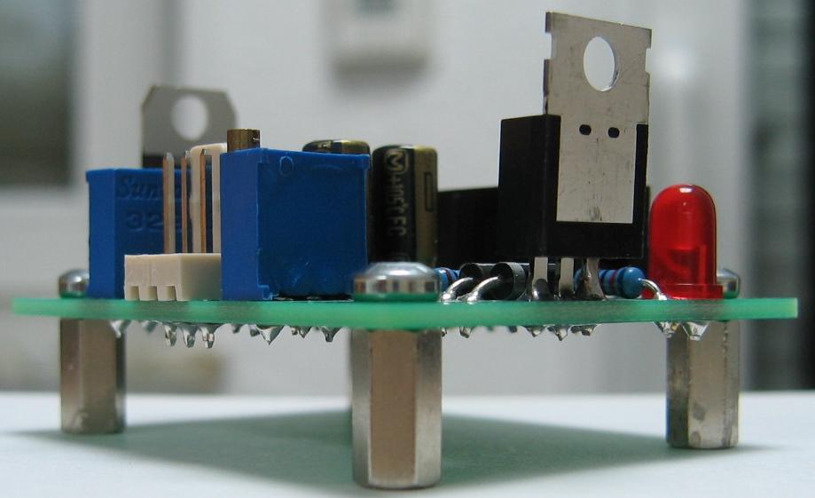
This circuitry is part of my NGF VCO Core 2. It make use of two transistors to heat the 3046. It works with the SMD and DIL Version as well. The given resistor values keep the current values and the power dissipation below the maximum ratings. T3 is used to measure the actual temperature. The voltage drop over T3 is direct proportional to the chip temperature. It is compared to the voltage at pin 2 of the 3046 which is derived from TR6. The temperature is easily adjusted with TR6. Between heating off and maximum temperature. The testing bridge is driven with a stabilized 10V voltage source. T4 and T5 are used as heaters. R41 and R43 limit the maximum current. The different values are selected with purpose to keep pin 13 of the 3046 (the substrate) the lowest negative point at the chip.
The below picture shows the graph temperature in deg. Celsius vs. Voltage in mV at pin2. It is quite linear. You can easily derive the needed voltage for your preferred temperature from the graph. The data were taken from a LM3046 SMD mounted on a PCB. The figures for the DIL Version are slightly different. They will show up on my website as well as some more details ASAP. Temperature was measured with Fluke 63 IR thermometer.
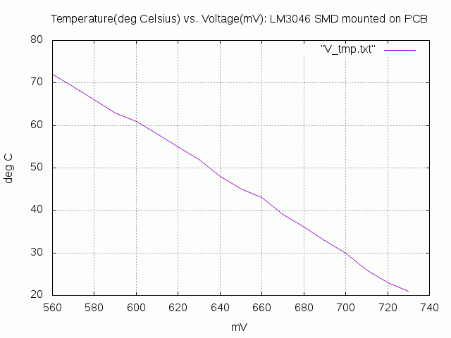
3046 heater: temperature vs. voltage plot