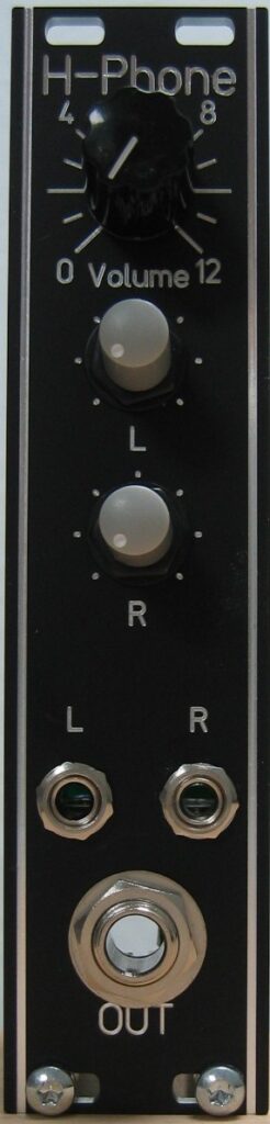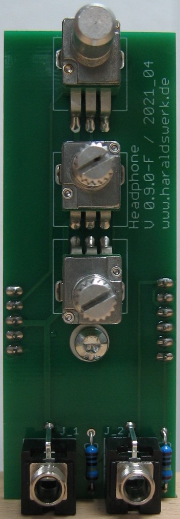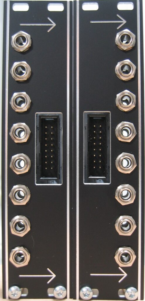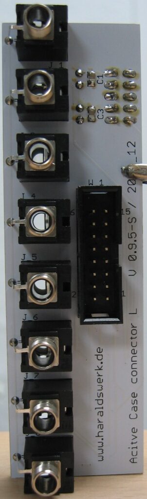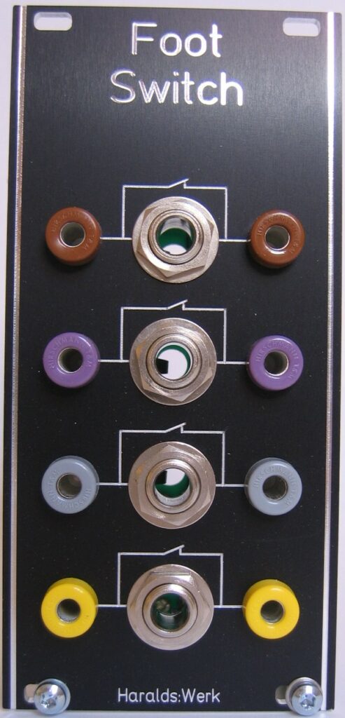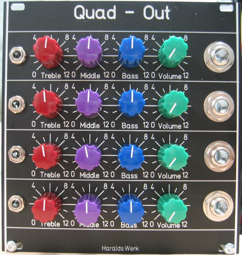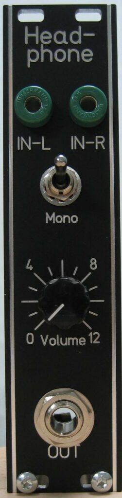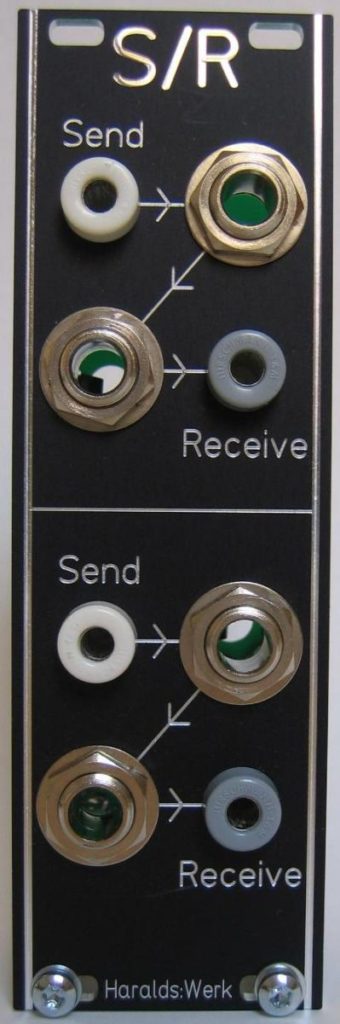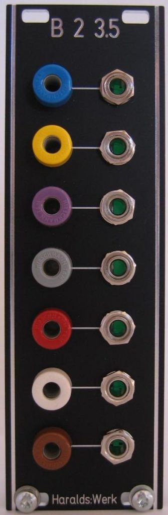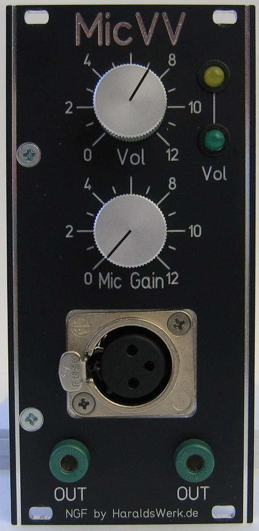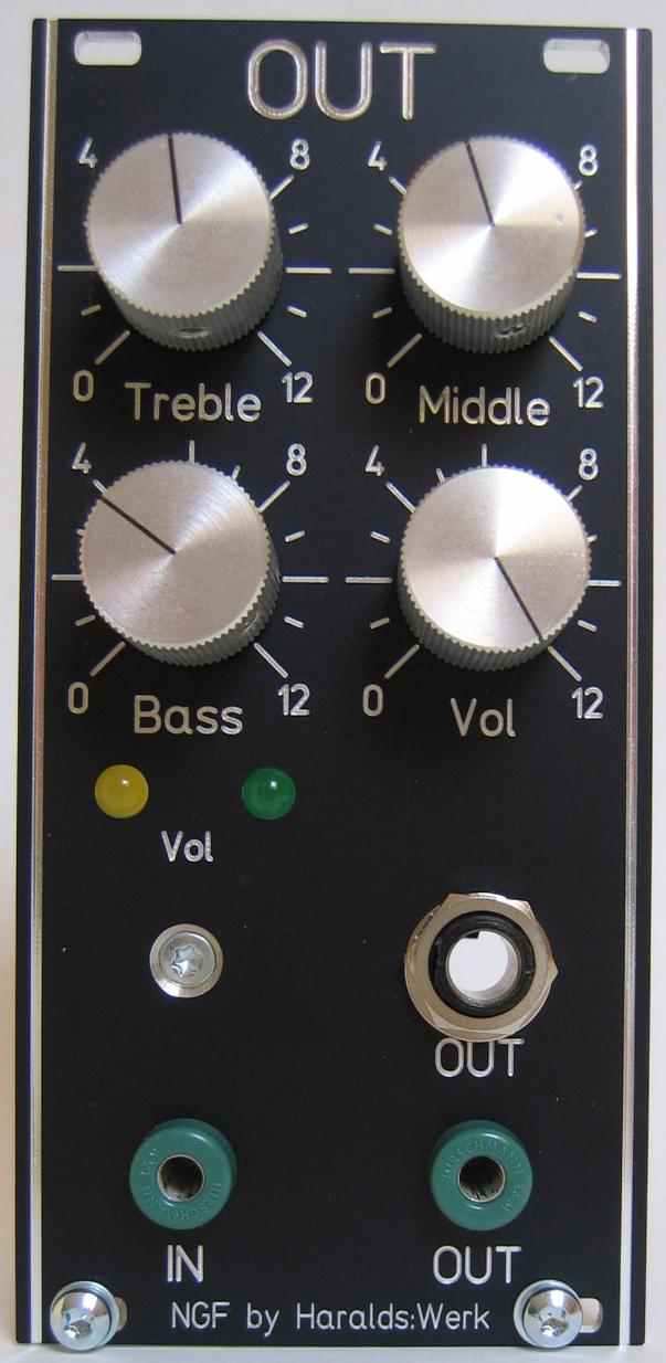
Output Module: Front view
This is my replacement of the original Elektor Formant COM module. I discarded the original circuitry because of the TL085 used with his unusual pinout and the availability of dedicated audio operational amplifiers. I used a more effective filter implementation for tone control. The tone control is derived from “Small Signal Audio Design” by Douglas Self Chapter 15. A optional level indicator makes it easier to find the right volume level for best SNR. The maximum output volume is adjustable to protect your PA. You can connect the output directly to active monitors.
Specs and features
• Bass, middle, treble tone control
• Adjustable maximum output volume
• Optional volume indicator
• Direct connection to active monitors
• Runs on +/-15V and +/-12V (with minor resistor changes)
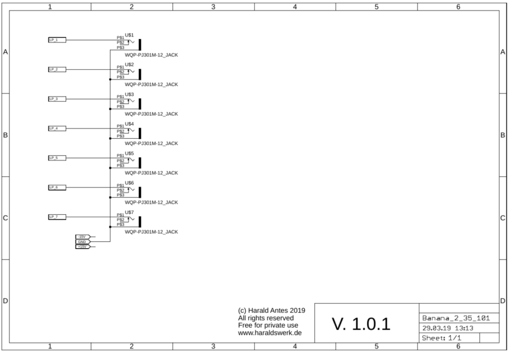
The documentation for download can be found in my website.
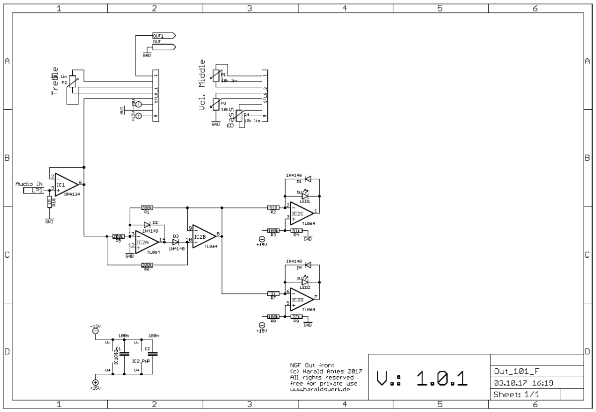
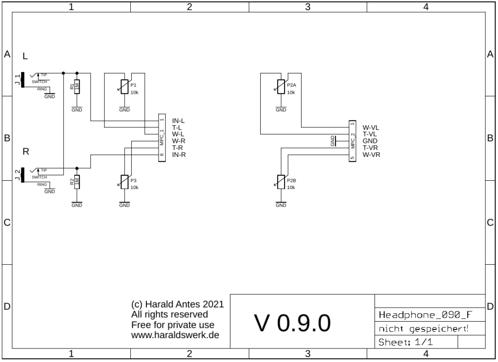
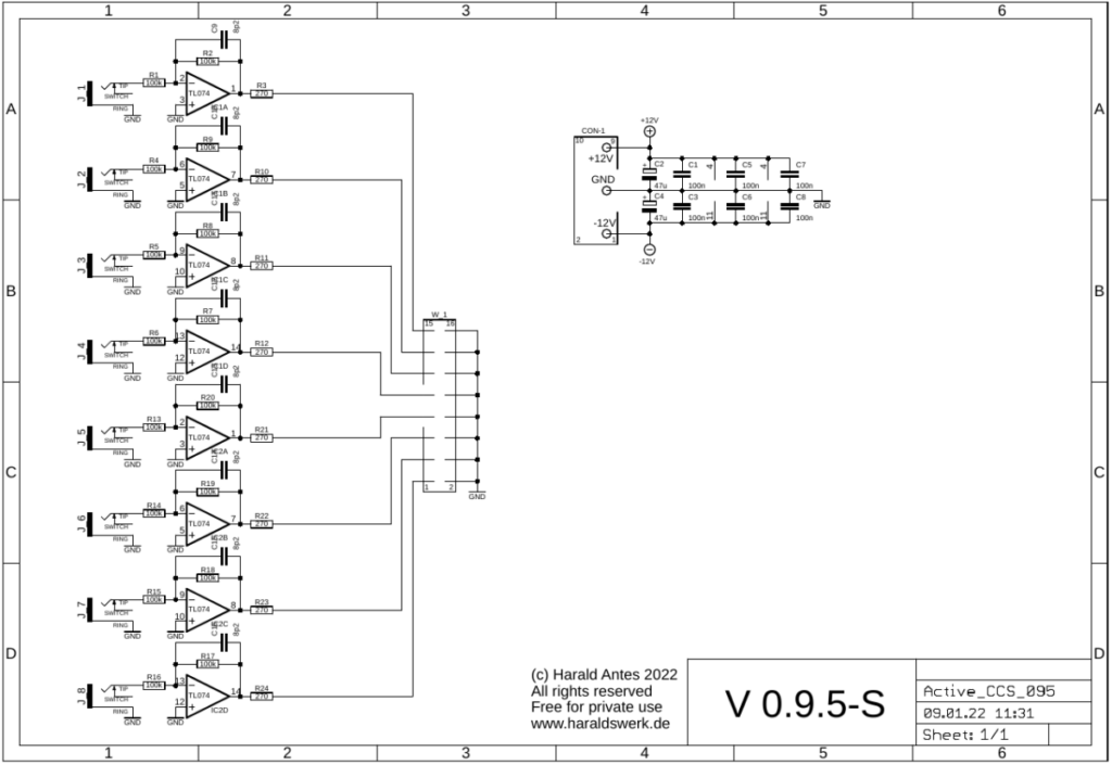
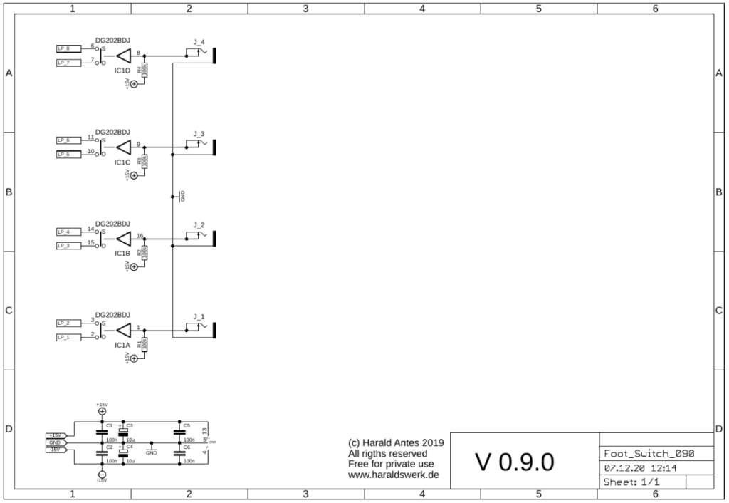
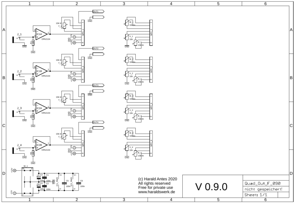
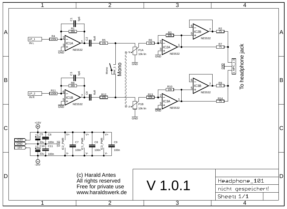
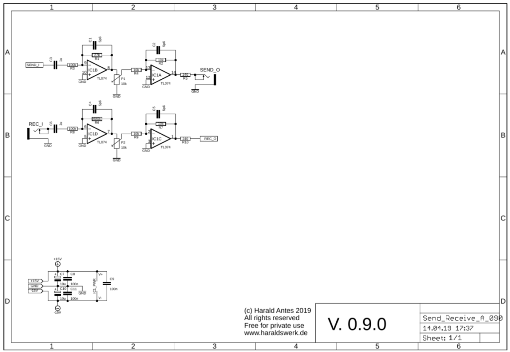
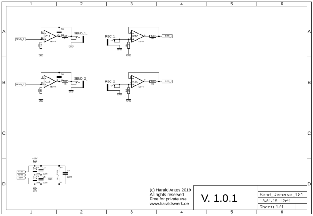
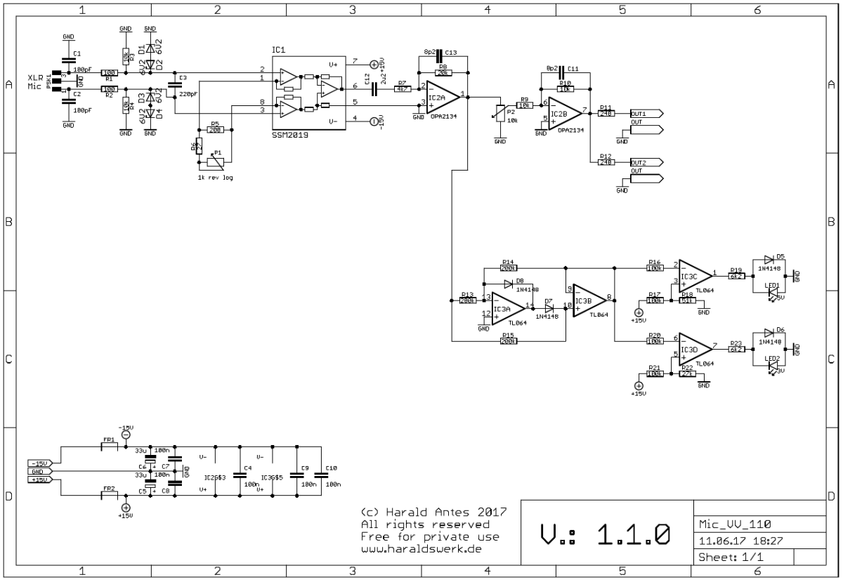
Output Module: Schematic front PCB
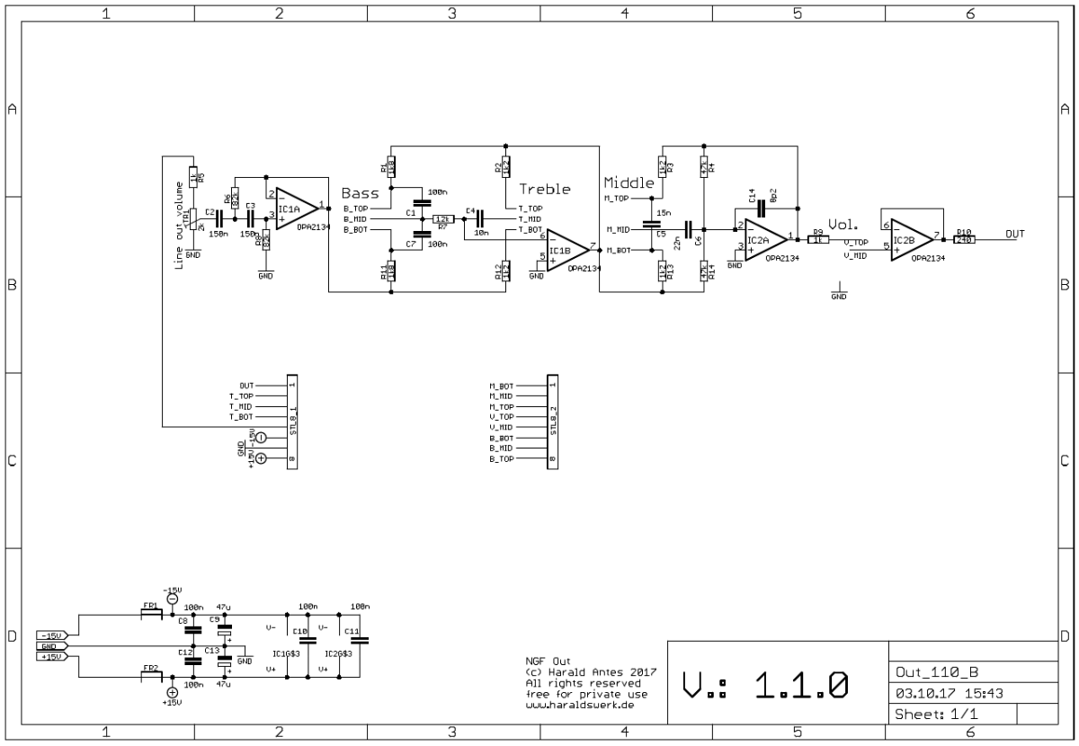
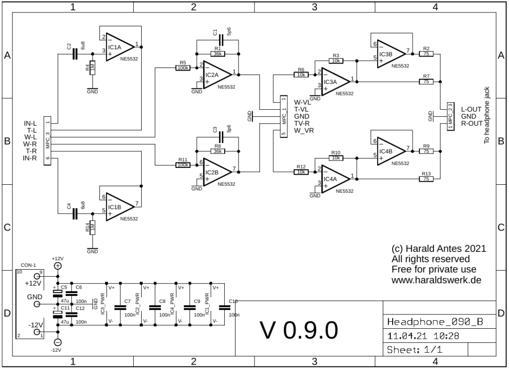
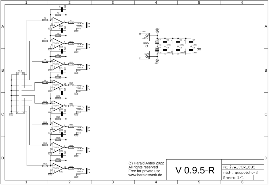
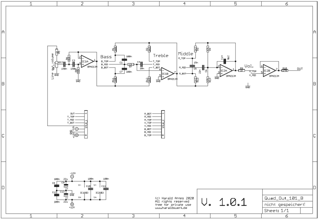
Output Module: Schematic back PCB
A description can be found in “Small Signal Audio Design” by Douglas Self Chapter 15
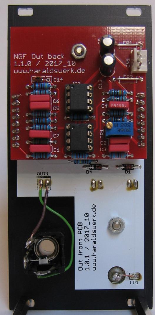
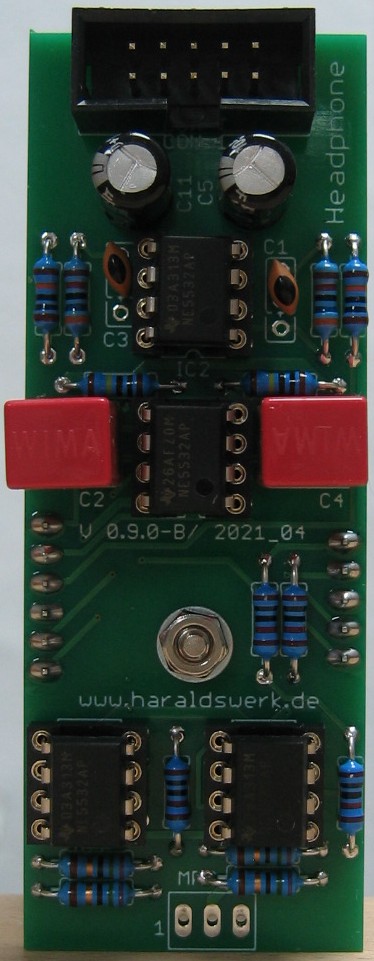
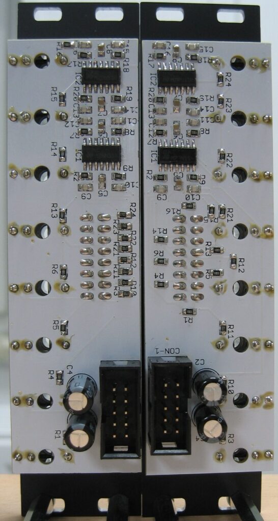
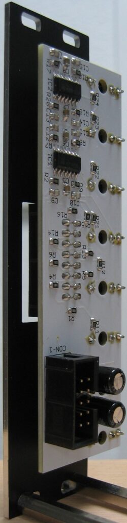
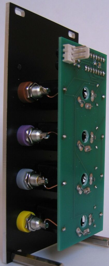
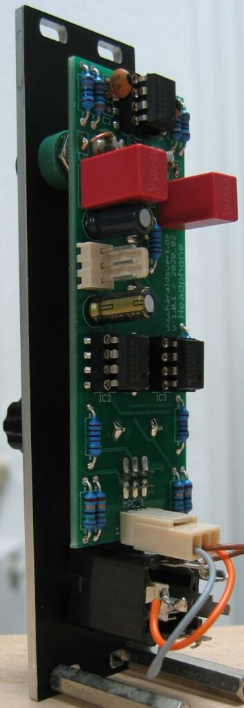
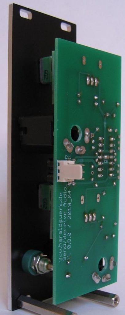
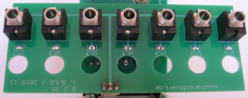
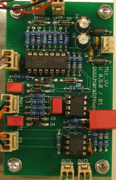
Output Module: Stuffed PCB back view
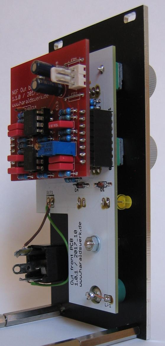
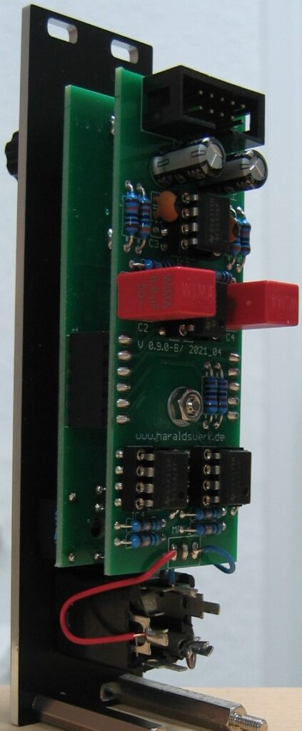
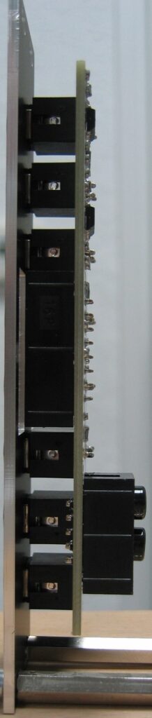
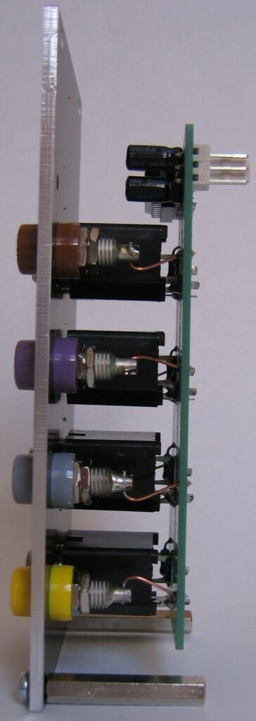
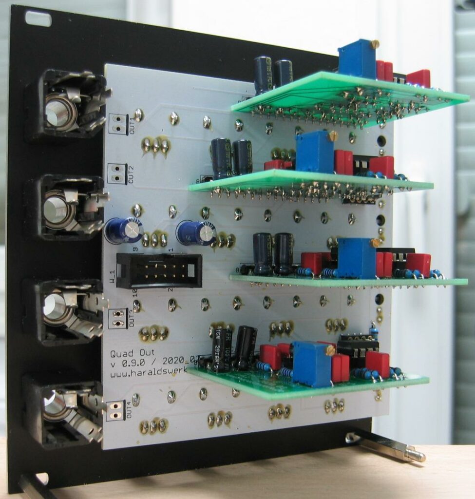
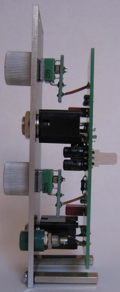
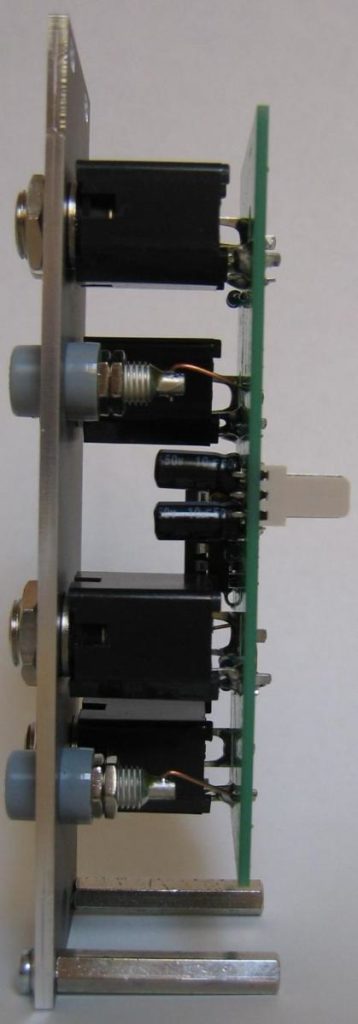
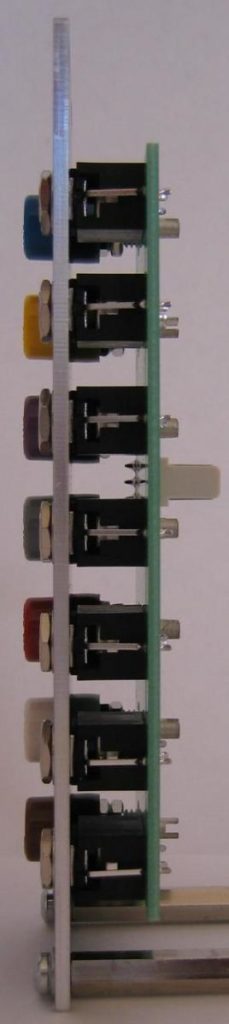
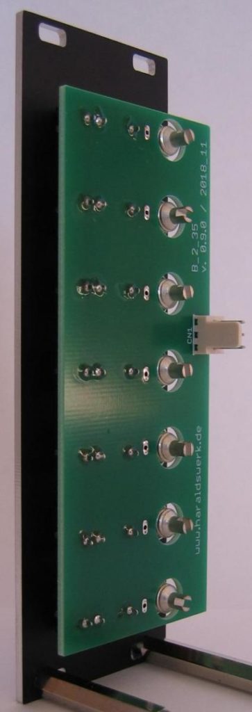
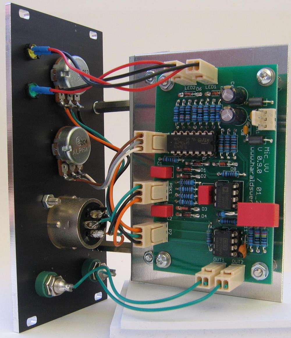
Output Module: Stuffed PCB side view
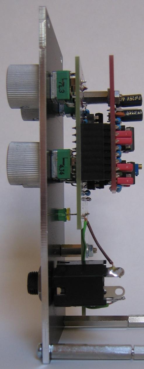
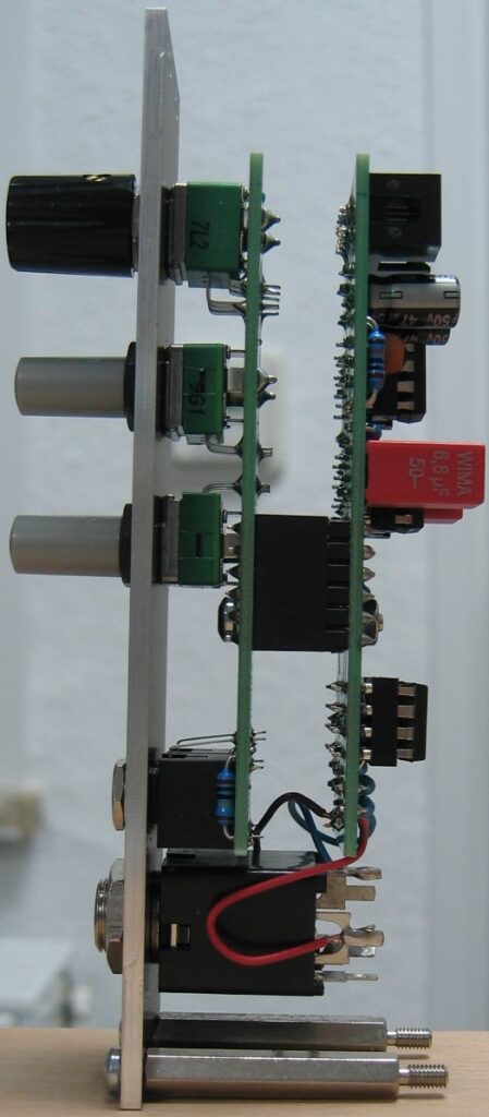
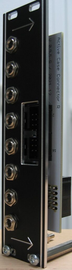
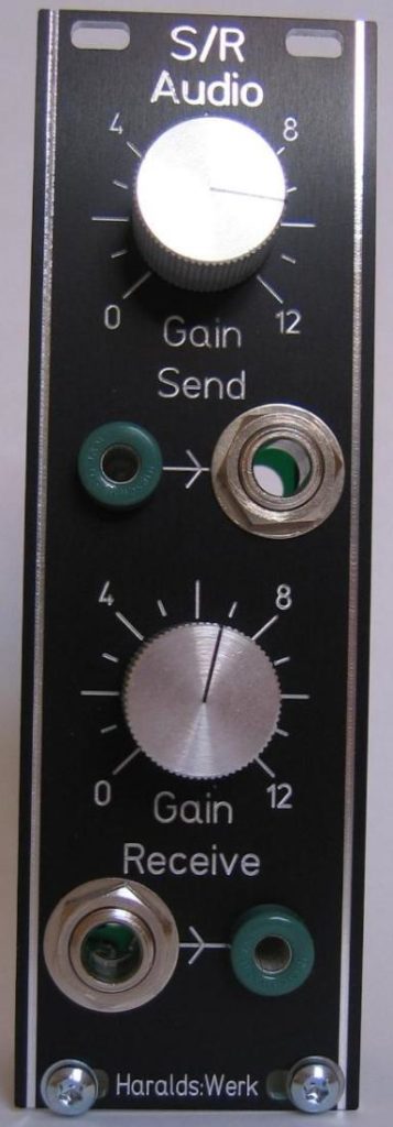
Output Module: Side view