Matched transistor-pairs are often needed while building modules for synthesizers. Especially for exponentiators and differential amplifiers. Not to forget the Moog style ladder filters. I build an transistor matcher for me many years ago and still use it. I know that there are easier matching circuits out there today but mine works great for me so there is no need to change. Mine is based on the original transistor matcher found in the “Technical Service Manual for Moog Modular Systems” on page 53. I added some circuitry for stabilizing the used voltages. That was done to be able to repeat the measurement without bothering about the power supply adjustment. We are dealing with 1mV – 2mV here!
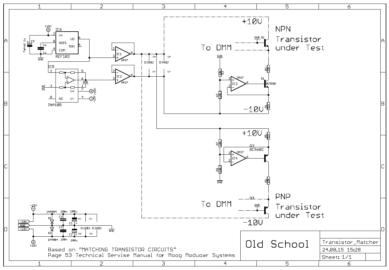
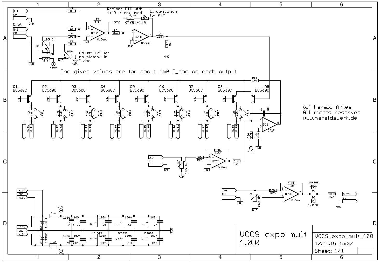
Transistor Matcher schematic
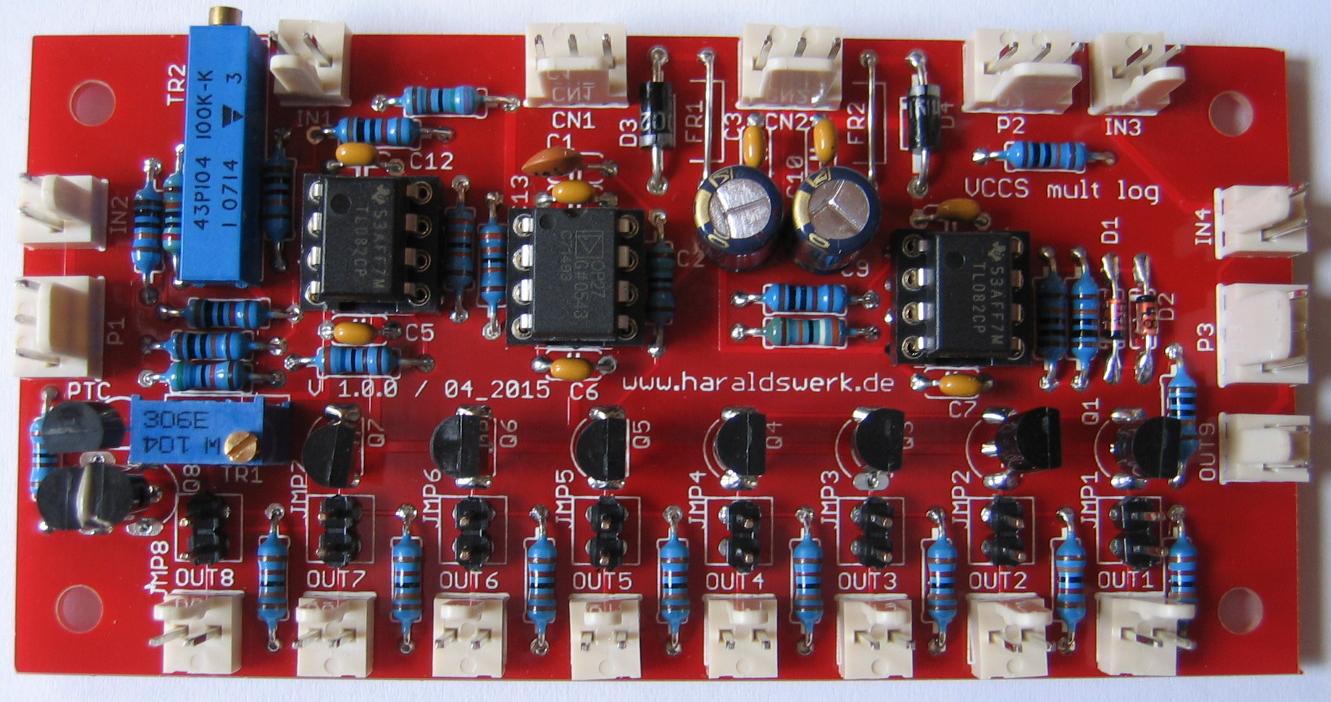
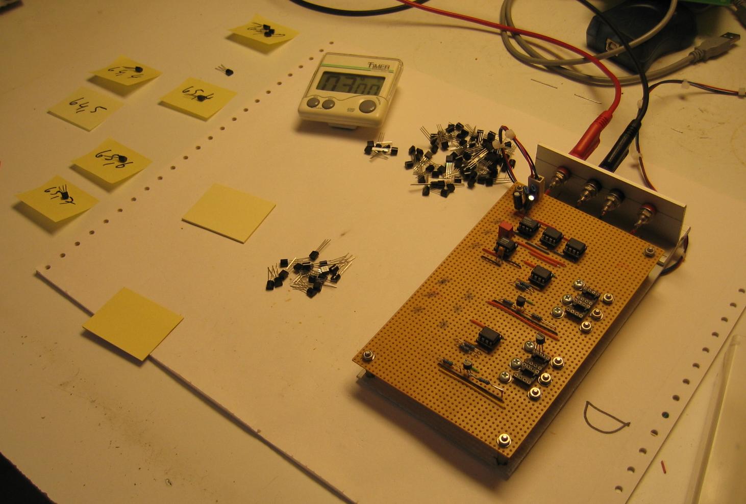
There was no need for a PCB. I just put it on perfboard and used IC sockets for the DUT.

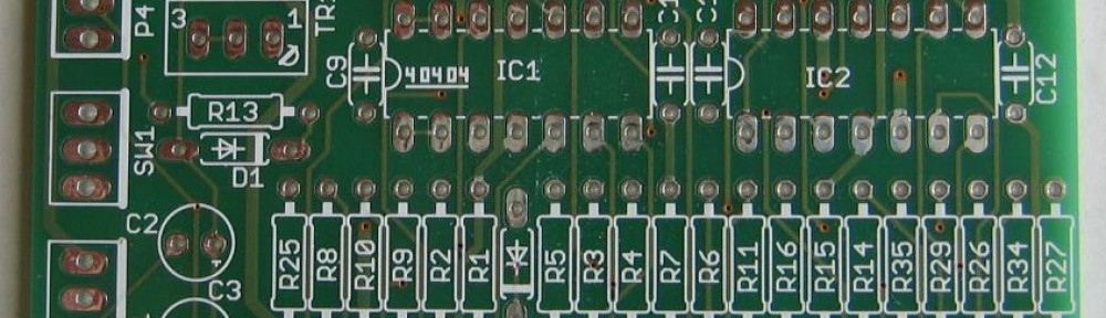
Transistor Matcher
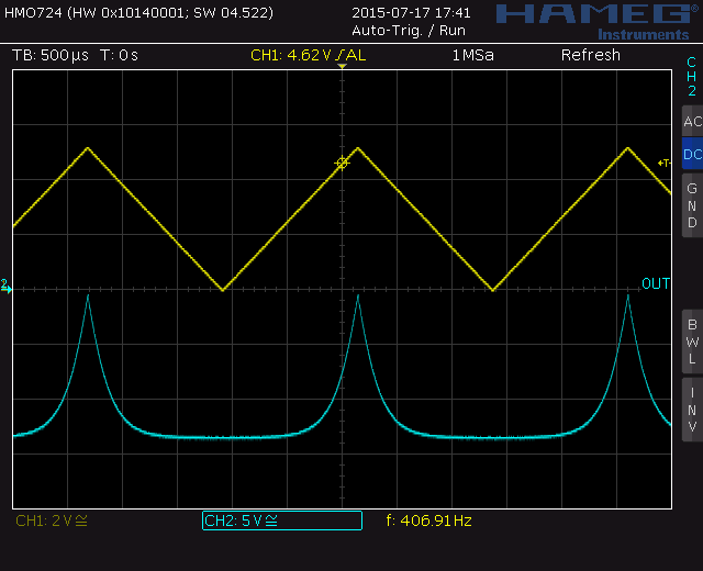
The usage is easy but you have to consider some precautions. The measurement is very temperature sensitive. You need to keep your environment stable. Use pliers to mount the DUT. Place the transistors into the socket. Measure base to emitter voltage. Don’t touch the transistors with fingers. The finger heat will cause the readings vary. Mark down the Vbe and find two transistors that the Vbe matches within 2mV or better.
Transistor Matcher usage
With today standards of fabrication transistors it is not unusual to find nearly every transistor within the 2mV Vbe range in a batch. You can easily match your pairs to better standards. Depending on your equipment 0.5mV Vbe match should be easily to reach. But always remember: The measurement is very sensitive. Be careful with your setup!