I have build my first synthesizer in the late 70’s. And I am playing Shakuhachi for seven years now. Time to bring both worlds together. Here we go.
The aim of this project is to provide shakuhachi players with the means to control an analogue synthesizer simultaneously with playing the shakuhachi, without affecting the playability of the flute.
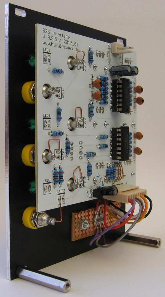
So far it consists of three main modules: the pitch-to-voltage converter, the envelope follower and the “E-Shak”. The pitch-to-voltage converter derives a voltage from the pitch played on the shakuhachi. This is used primarily to control the pitch of the VCO (which is the initial generator of waves in the synthesizer). The envelope follower provides a voltage which follows the volume of the shakuhachi, together with gate and trigger signals. These are used mainly in conjunction with the synthesizer’s VCA (which is responsible for the dynamics of the synthesizer’s signal). The “E-Shak” is an exoskeleton attached to the shakuhachi with crepe tape. It is equipped with an accelerometer with three axes and with three switches. This module provides three control voltages according to the movement of the shakuhachi, and three additional on/off switches. The usage is only limited by the player’s imagination.
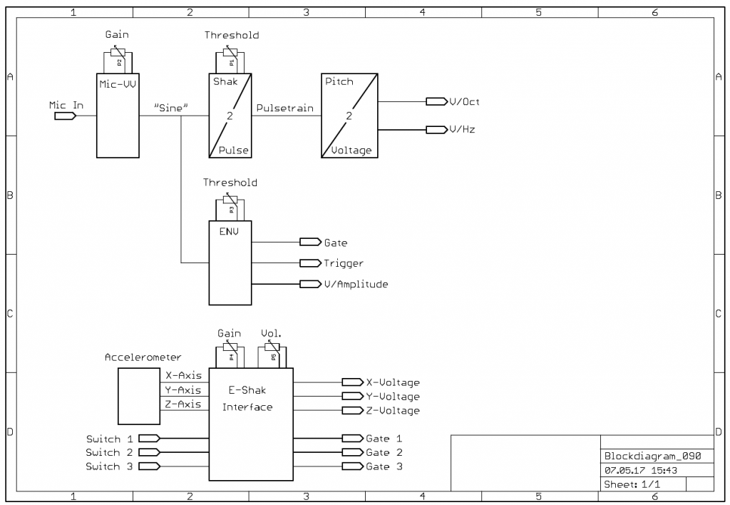
Shakuhachi 2 Synth project: Block diagram
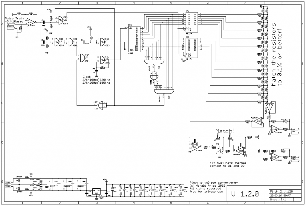
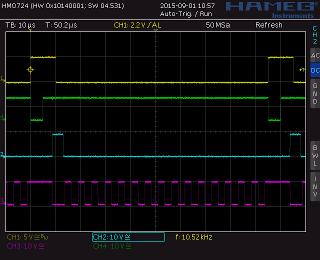
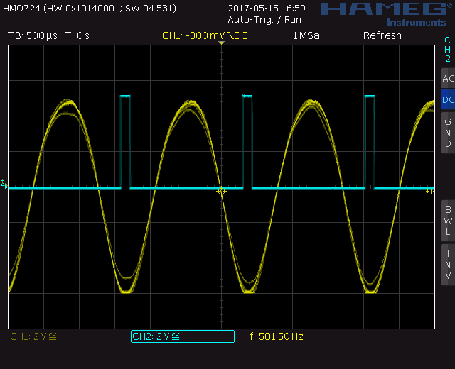
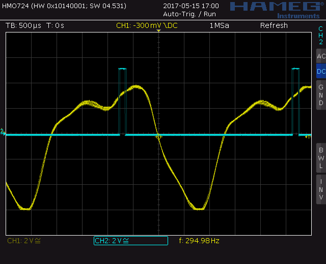
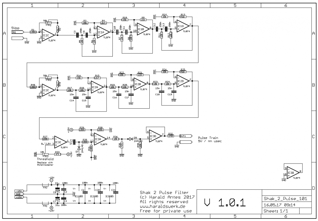
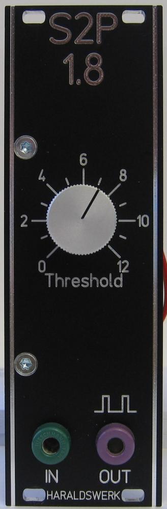
In the block diagram you can see the basic structure of the project. The microphone signal goes to the “Shak 2 Pulse” converter and the envelope follower (ENV). The Shak 2 Pulse converter is a band pass filter followed by a zero crossing detection with adjustable threshold. The output is a pulse train with the same frequency (pitch). This pulse train is converted to a voltage according to the pitch. The output voltage is available in V/Hz and V/Oct format. The envelope follower generates the gate (+5V), the trigger (+5V/20ms) and a voltage following the amplitude of the microphone signal.
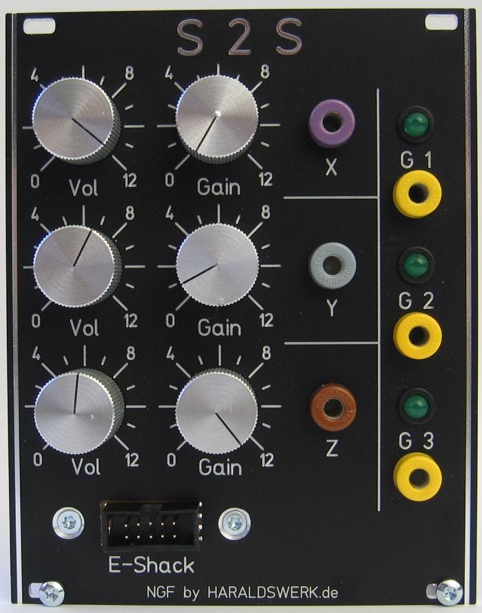
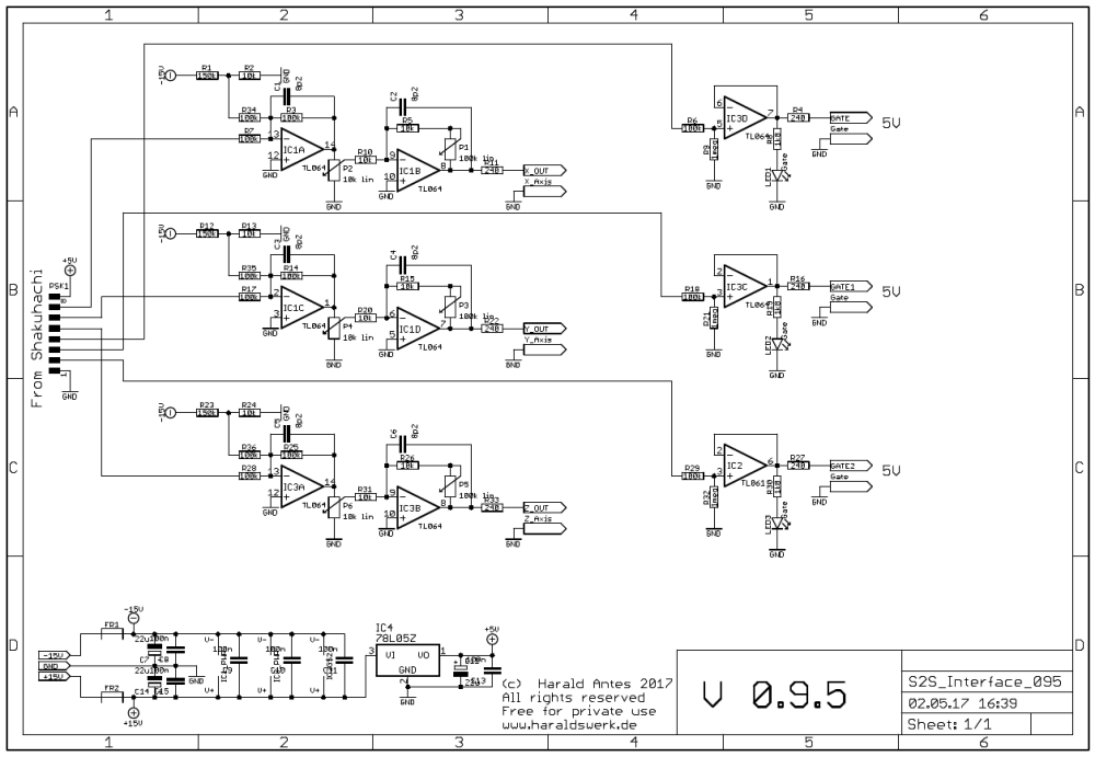
The “E-Shak” is an exoskeleton equipped with a three axis accelerometer and three touch sensitive switches. With the interface you can adjust the gain and the inclination of the accelerometer signal. It provides three gate signal (+5V) as well.
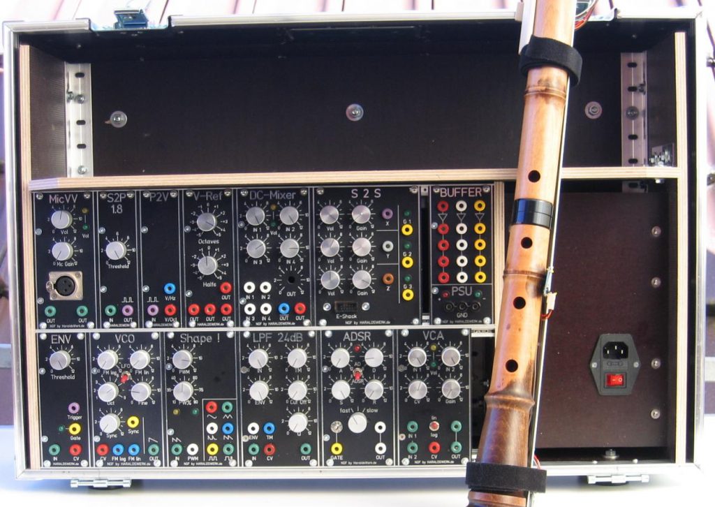
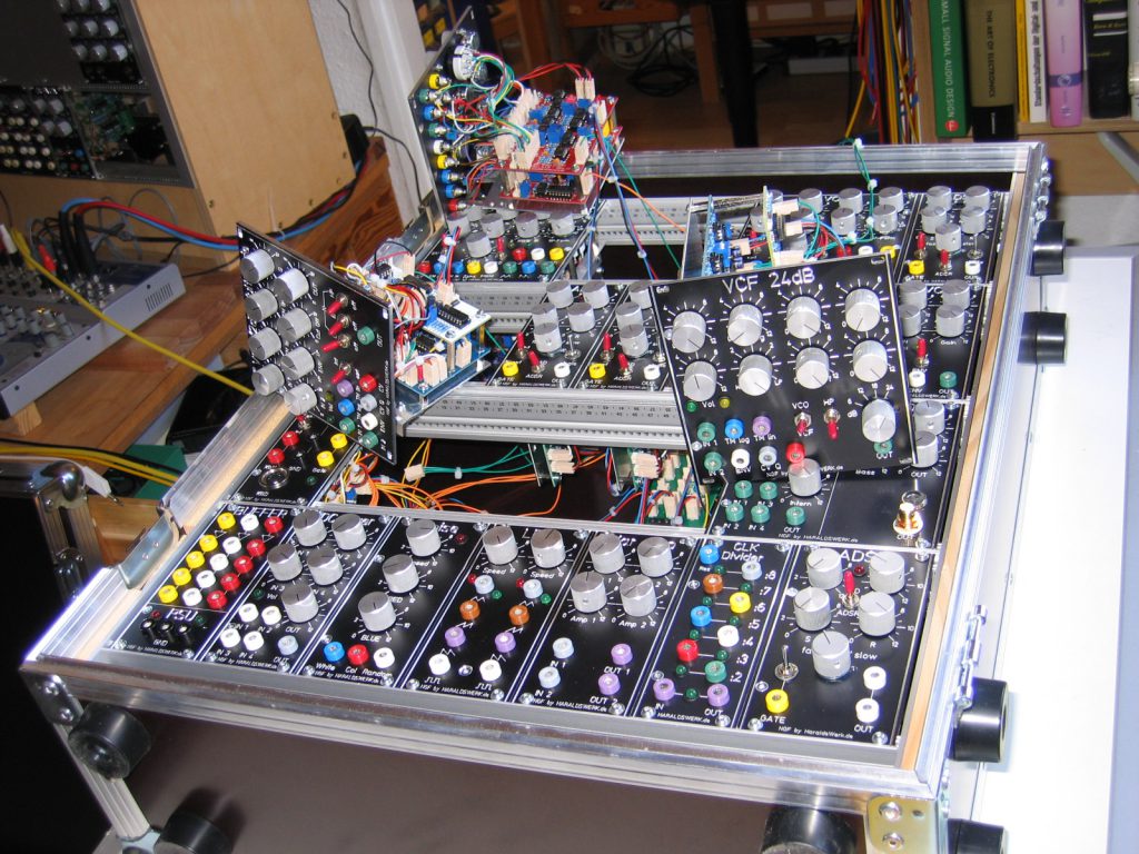
Shakuhachi 2 Synth project: stuffed flight case