Compressor with optional pedal steering

Compressor: Font view

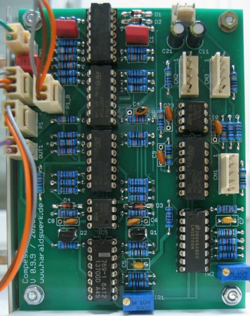
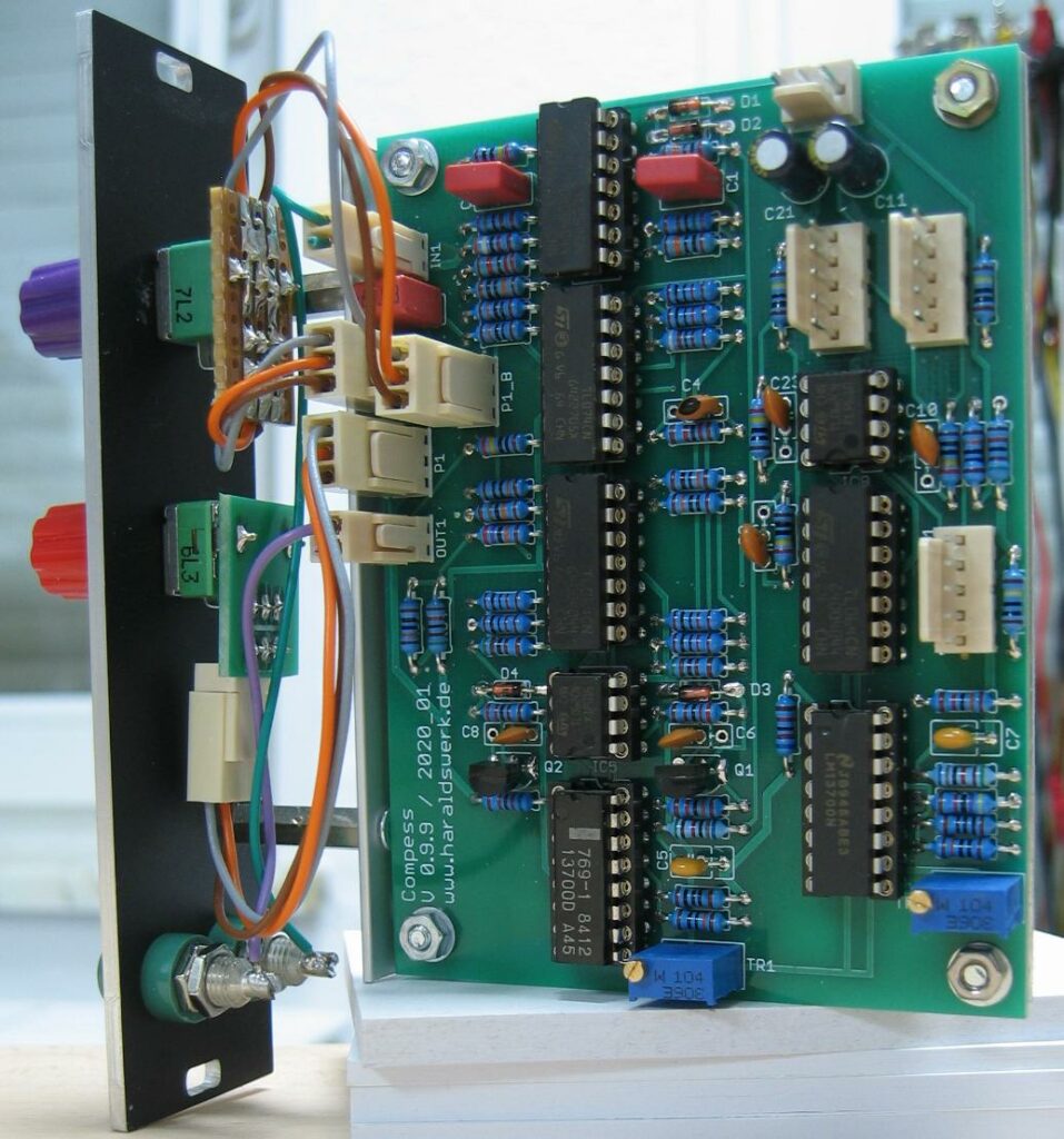
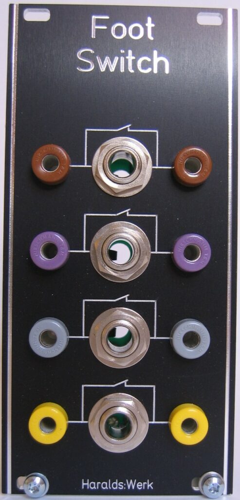
This is the revised version of my Limiter/Compressor. First built for my Shakuhachi to Synth project to handle the great dynamic range of the Shakuhachi. Here I left out the limiter and added a make up amplifier. The structure used is derived from “Small Signal Audio Design”, second edition by Douglas Self p682ff. The audio signal did not flow through a VCA as in many other implementations. Instead the compression is done by subtracting the audio signal at the output summing node according to the control voltage derived from the audio signal. The compression rate and the make up gain is adjusted by hand or/and optionally with foot pedals. The foot pedals are an additional option particularly made for wind players. It works without this option in your setup as well.

Specs and features

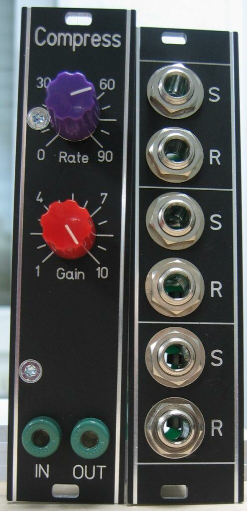
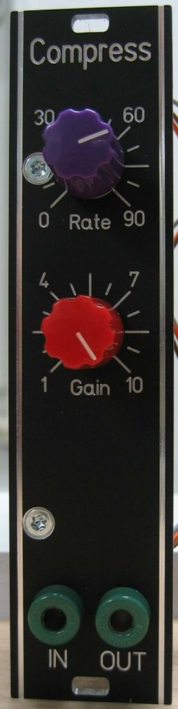
  • Compression rate and gain adjustable by hand or/and foot pedals
  • Audio path not affected when no compression is used
  • Runs on +/-12V and +/-15V (with minor resistor value changes for best performance)
  • Power consumption below 20mA each rail

The documentation and the Gerber files for download can be found in my website.

Compressor: Schematic

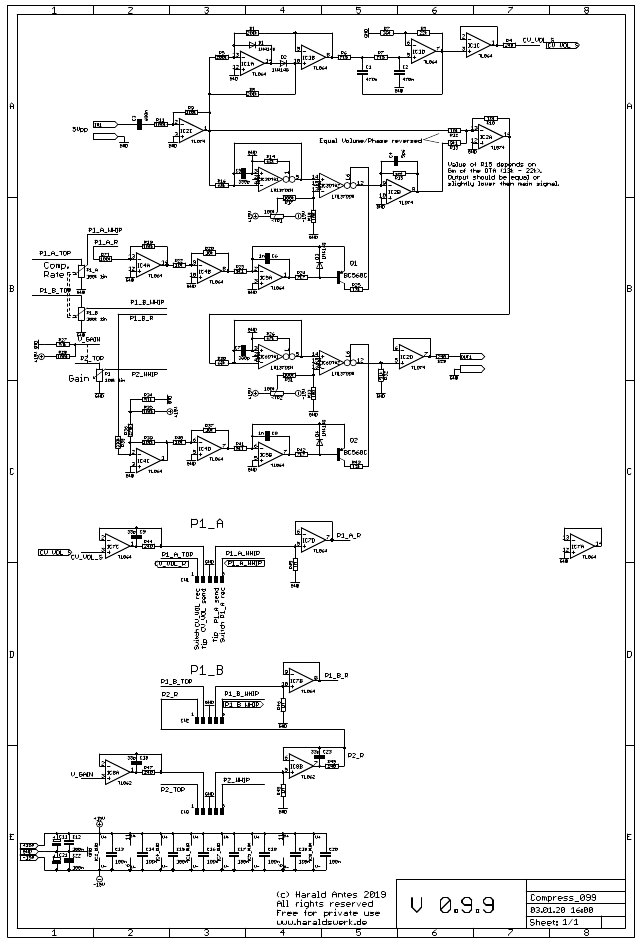
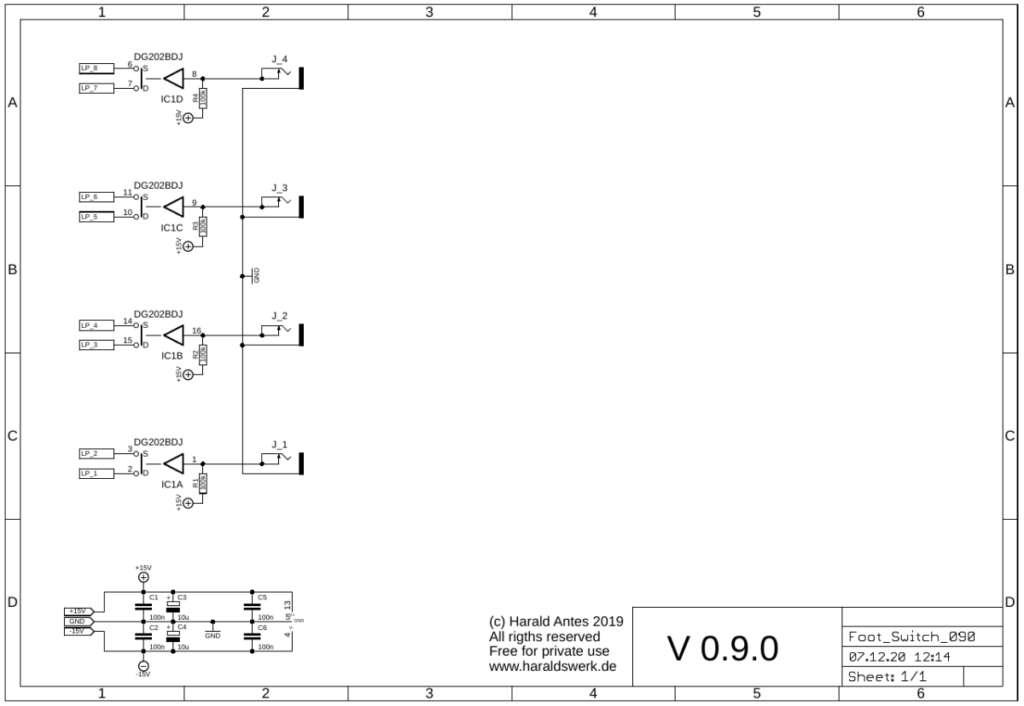
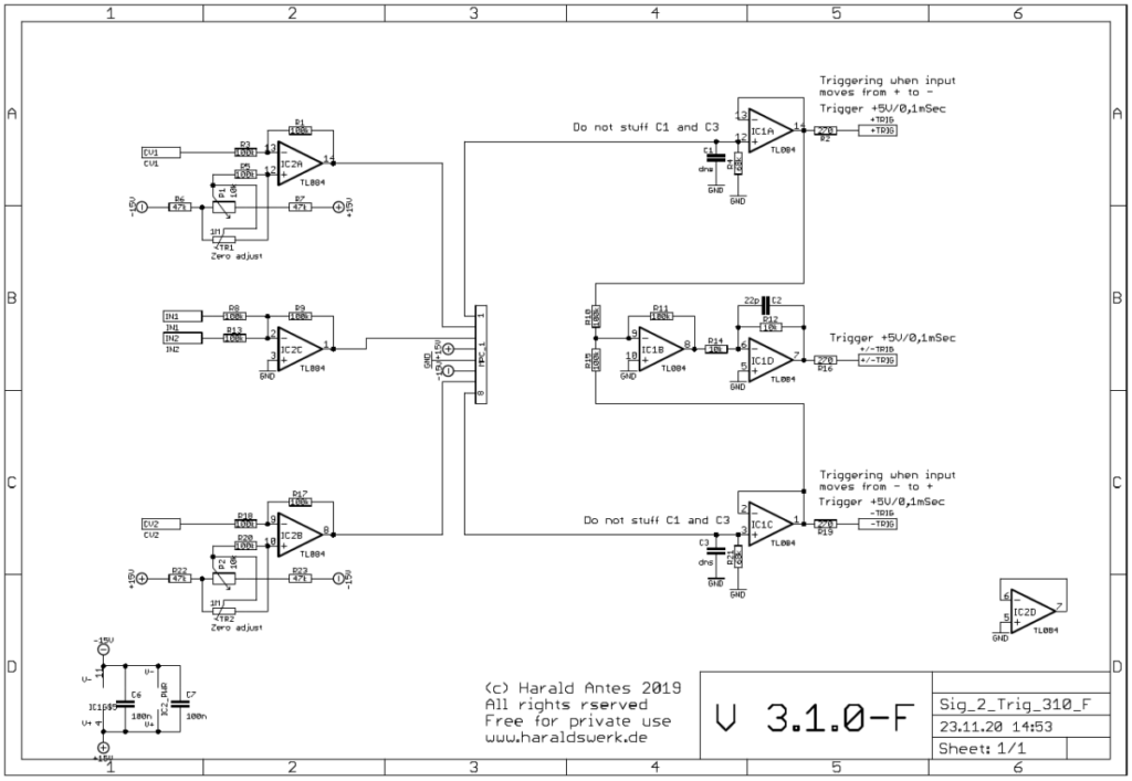
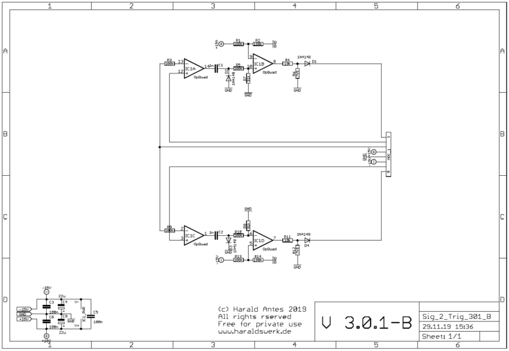
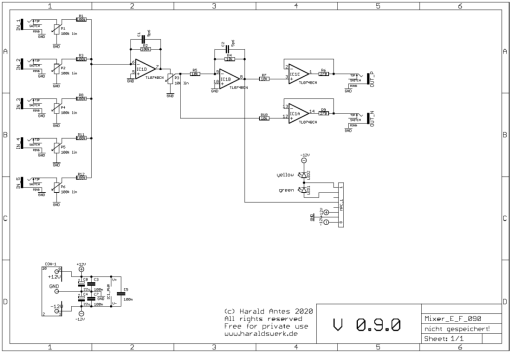
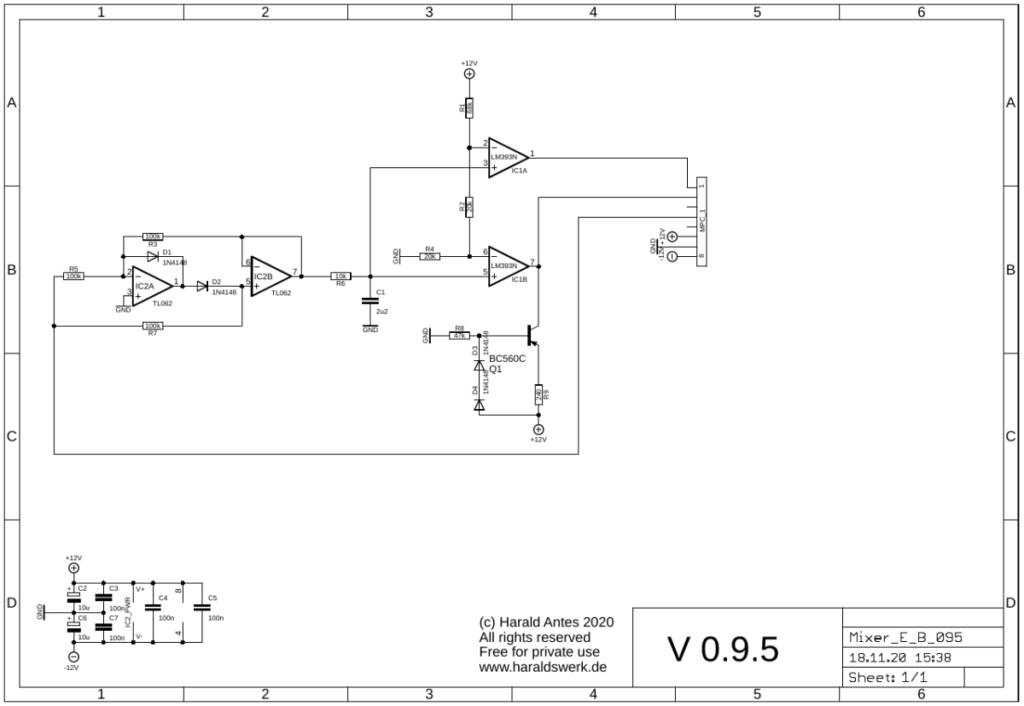
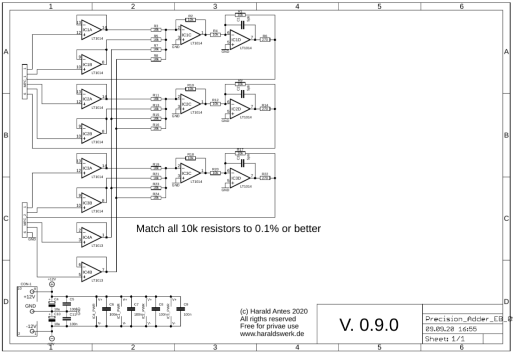
When the ratio is set to zero and the gain to one the input signal passes through the circuitry unaffected (IC2C, IC2A IC6OTA1, IC6OTA2, IC2D). When the compression rate is turned up a DC voltage is derived from the input signal wit a precision full wave rectifier and some filtering (IC1A, IC1B, IC1C, IC1D). This voltage is used to open the VCA in the side chain (IC3OTA1, IC3OTA2, IC2B). The signal from the side chain is then subtracted from the main signal (R13, IC2A). The now compressed signal is then potentially amplified (IC6OTA1, IC6OTA2)

Compressor: Populated PCB
Compressor: Back view
Compressor: Front with pedal connector

Foot switch connector

Foot swithc connector: Front view

As a Shakuhachi player I need my hands on the flute. So I use me feet to manipulate parameters and switches on the synthesizer. This module was originally build for my Shakuhachi to Synth project to provide the possibility to connect foot switches with the synthesizer and keep the patch intact when they are removed. The signal is not routed through the foot switch. Instead CMOS switches are used, turned on and off with the foot switch. So the signal stays within the synthesizer and the connection to the foot switch carries only DC. Removing the foot switch does not interrupt the signal flow in the synthesizer.

Specs and features

  • Four independent switches
  • Signal flow stays intact when foot switch removed
  • Runs on +/-15V and +/-12V
  • Power consumption below 10mA each rail

The documentation and the Gerber files for download can be found in my website.

Foot switch connector;: Schematic

The switch in the DG202 is hold in on position with a 100k resistor against the positive rail. With a foot switch attached you can pull down the hold voltage when you close the foot switch.

Foot switch connector: side view
Foot switch connector: Back view

Signal to Trigger Converter

Signal to Trigger Converter: Front view

This module was originally build for my Shakuhachi to Synth project to provide the start/stop pulse for the Pitch to voltage converter. But it turned out to be much more useful. When you have the basics for your synthesizer like VCO, VCF, VCA, ADSR, LFO,… and some controllers and you want more, then using your keyboard to steer the synthesizer it is time for some modules to produce trigger signals out of different sources. Here is one of them. A signal to trigger converter. You can feed in a changing signal and every time the signal went through zero a trigger is generated dependent on the direction from where the zero point is crossed. You can add a threshold manually or CV controlled to move the zero point up or down as well. You can feed the signal in through input one ore two. When both inputs are used the signals are added together. When the signal crosses zero from positive to negative a trigger of about 0.1msec is generated at output -Trig. When the signal crosses zero from negative to positive a trigger of about 0.1msec is generated at output +Trig. Output +/-Trig provides both triggers. This output can be used to generate interesting rhythmic patterns when the threshold is set by a slowly moving CV or some DC offset is applied to the signal.

Specs and features

  • Two added inputs
  • Threshold manually and with CV
  • Output for +Trig, -Trig and +/-Trig: 0.1msec
  • Runs on +/-15V and +/-12V with minor resistor changes
  • Power consumption below 25mA each rail

The documentation and the Gerber files for download can be found in my website.

Signal to Trigger Converter: Schematic control board
Signal to Trigger Converter: Schematic main board
Summed signal to trigger

The incoming signals are summed up. Every time when the summed signal changes polarity (moving through zero) a trigger is generated. Moving from plus to minus generates a trigger at the negative trigger output, moving from minus to plus generates a trigger at the positive trigger output. Trigger length is about 0.1msec.

Screenshot sine to trigger

The uppermost line (Yellow) shows the input signal. The second line (Blue) shows the trigger when the input signal moves to the positive site. The third line (Purple) shows the trigger when the input signal moves to the negative site. On the fourth line (Green) you can see both triggers added. This picture is taken without any threshold.

Signal to Trigger converter: Back view
Signal to Trigger converter: Side view

Passive Multiple

Passive Multiple: Front view

Just another often needed utility module. A passive multiple.

Specs and features

  • Seven passive parallel in/outs
  • No power connection

The documentation and the Gerber files for download can be found in my website.

Passive Multiple: schematic
Passive Multiple: back view
Passive Multiple: Side view

Mixer, DC coupled with volume indicator

Mixer: Front view
Mixer: Front view

This is an often needed utility module. The mixer comes in handy for mixing CV sources and audio sources as well. This version is DC coupled, so you can use it for AC and DC mixing. There is an inverted output added. You can reverse the DC-CV mix with it or experiment with feedback loops in the audio domain. The added volume indicator us useful for finding the appropriate signal level. The volume indicator is optional. You can leave it out with no problems for the other functions.

Specs and features

  • Five inputs
  • Inverted and non- inverted output
  • Volume indicator (optional)
  • Runs on +/-12V and +/-15V
  • Power consumption below 20mA each rail

The documentation and the Gerber files for download can be found in my website.

Mixer: Schematic control board

Control board: Straight forward design. The mixer is completely DC coupled. So you can use it for CV mixing as well as audio mixing. IC1D sums the five inputs and inverts the signal. P3 is used to adjust the overall signal level. IC1B inverts the signal again. IC1C and IC1A buffers the outputs.

Mixer: Level indicator

Level indicator: The circuitry around IC2 build an precision full wave rectifier. The output is smoothed with C1. The parts around the BC560C build a constant current source for driving the LED’s. The comparator LM393 (IC1A/B) switches the LED on and off according to the input level.

Mixer: Populated control PCB
Mixer: back view (with populated level indicator board)

Precision Adder

Precision Adder front view

This is a useful and often needed utility module. The input voltages are precisely added to the outputs.The inputs 1, 3 and 5 are normalized. It can be used in different ways: As three independent adders, as buffered multiple, adding a modulation source simultaneously to all three outputs, adding two, three or four voltages precisely and a few more, depending on your patch. The accuracy depends on the used operational amplifier. For pitch CV I recommend precision OpAmps like the LT1014.

Specs and features

  • 3 independent precision adders
  • Input 1, 3 and five normalized
  • Buffered multiple
  • Additional common modulation inputs
  • Runs on +/-12V and +/-15V
  • Power consumption below 10mA each rail

The documentation and the Gerber files for download can be found in my website.

Precision Adder schematic main PCB
Precision Adder schematic control PCB

All inputs are buffered with high impedance inputs. They are followed by precision adders where the two inputs and the two additional modulation inputs are added together. The last stage buffers the output and corrects the phase. Inputs 1, 3 and 5 are normalized. The accuracy depends on the used operational amplifier and the matching of the resistors. For pitch CV I recommend precision OpAmps like the LT1014. Match all 10k resistors to 0,1% or better.

Precision Adder side view
Precision Adder populated PCB

15V to 12V adaptor

15V to 12V adaptor populated PCB

From time to time I want to integrate a 12V Eurorack module in my 15V banana setup. So I needed a 15V to 12V adaptor. Nothing spectacular. Just from the datasheet. This is the bigger brother for up to five modules from the single one.

Specs and features

  • Input +/-15V DC (or higher)
  • Output +/-12V DC

The documentation and the Gerber files for download can be found in my website.

15V to 12V adaptor schematic

Just the standard configuration from the datasheets.

15V to 12V adaptor front view
15V to 12V adaptor side view

Buffered Multiple

Buffered Multiple front view

This is a useful and often needed utility module. The input voltage is precisely reproduced on the outputs. It comes in handy when you need to distribute signals which must be decoupled. The input signal is buffered and decoupled with means of individual operational amplifiers. One input drives 6 individual outputs. The accuracy depends on the used operational amplifier. For pitch CV I recommend precision OpAmps like the LT1014 (quad) and LT1013 (dual).

Specs and features

  • 6 independent buffered outputs
  • Runs on +/-12V and +/-15V
  • Power consumption below 10mA each rail

The documentation and the Gerber files for download can be found in my website.

Buffered Multiple schematic 01
Buffered Multiple schematic 02
Buffered Multiple side view
Buffered Multiple back view
Buffered Multiple populated main PCB

Headphone output

Headphone amplifier/output front view

Not that much to say here. Simply a Headphone amplifier. Based on Douglas Self “Small Signal Audio Design” second edition pg.560 and pg.33 fig.1.12

Specs and features

  • Drives headphones in the range from 50R to 600R
  • Runs on +/-15V and +/-12V
  • Power consumption around 25mA each rail

The documentation and the Gerber files for download can be found in my website.

Headphone amplifier schematic

Simple dual amplifier with opamp-array (multipath amplifier).

Headphone amplifier back view

Scaled voltage reference with octave and semitone steps

Scaled voltage reference with octave and semitone steps. Front view

This module provides high precision CV outputs in 1V (octaves) and 83,3mV (halves) steps. The 1V output goes from -5 to +5V. The 83,3mV steps goes from -5 to plus 5 steps (halves). This module is thought for all who are missing octave switches in some modules. Especially in VCO. With this module you can switch octaves and halves as well.

Specs and features

  • High precision output 0-8V in 1V steps (octaves)
  • High precision output in 83,3mV steps, +/- 5 steps (Halves)
  • Runs on +/-15V and +/-12V
  • Power consumption around 30mA each rail

The documentation and the Gerber files for download can be found in my website.

Scaled voltage reference with octave and semitone steps. Populated PCB
Scaled voltage reference with octave and semitone steps. Schematic

The precision voltage is derived from the REF102. The negative voltage is provided with the INA105. It is crucial to match the resistors in the voltage dividers as good as you can. The outputs of the voltage dividers are buffered to avoid loading of the dividers. The resistors around the OpAmps must be matched as well. The one volt and the 83,3mV steps are added together with IC4A. The three outputs are individual buffered.

Scaled voltage reference with octave and semitone steps. Populated PCB