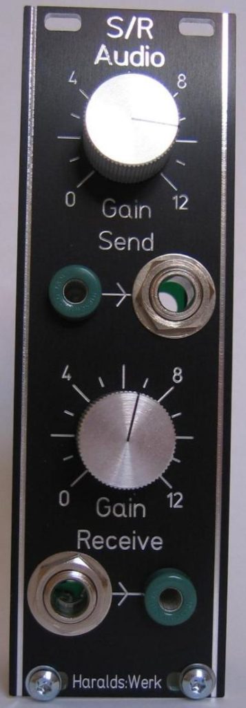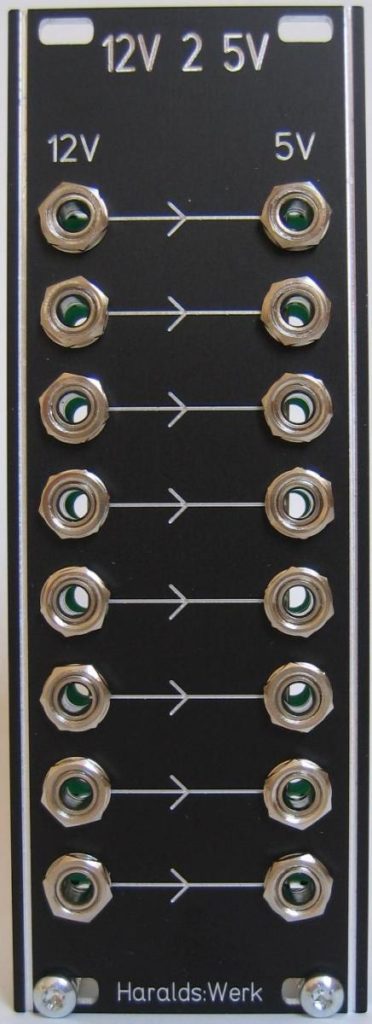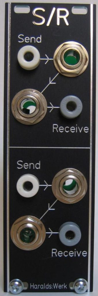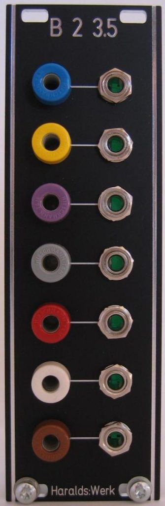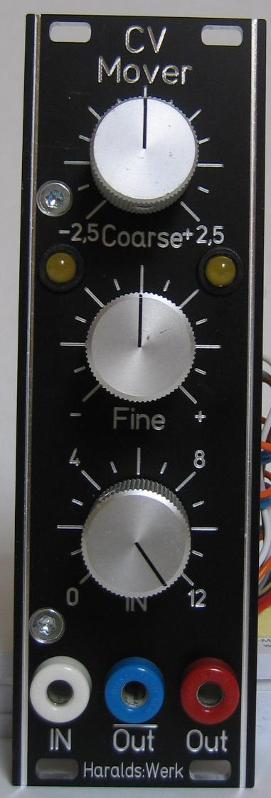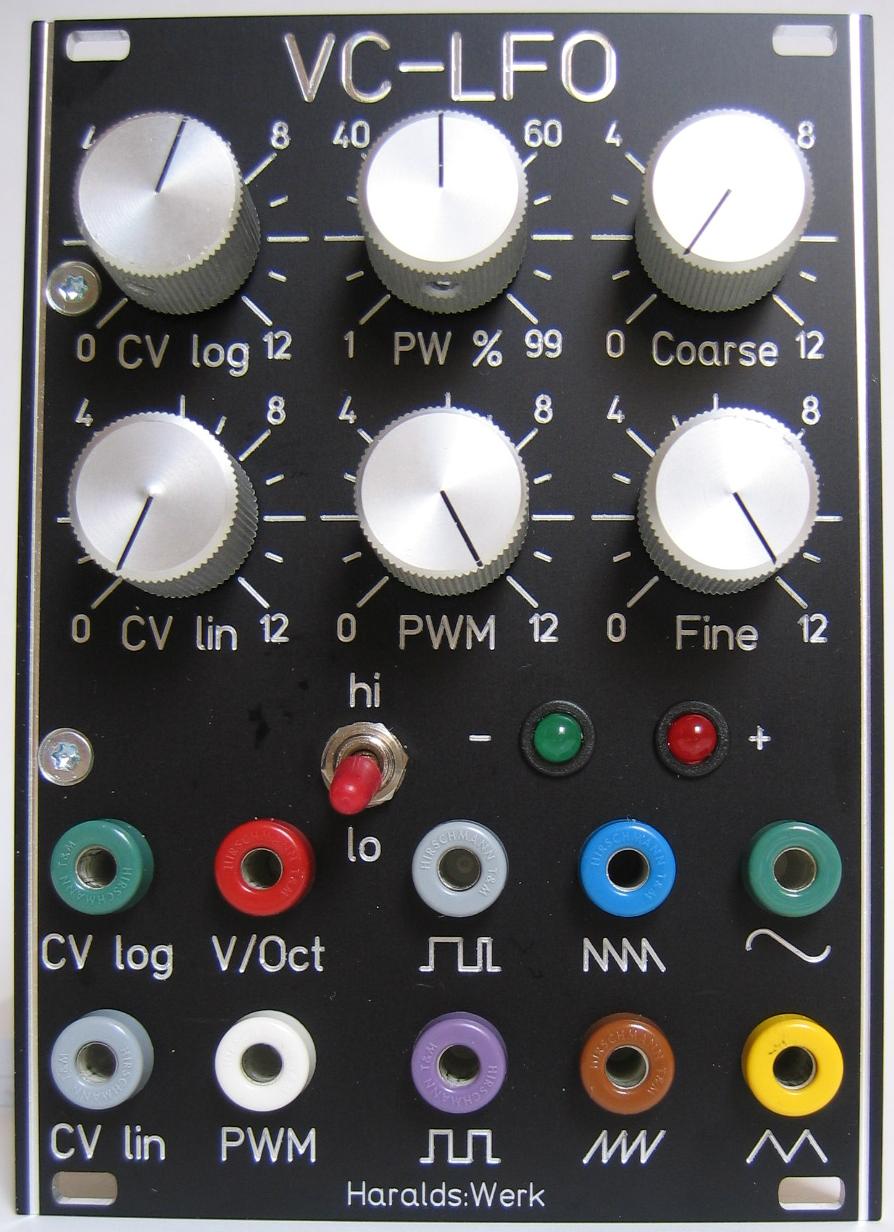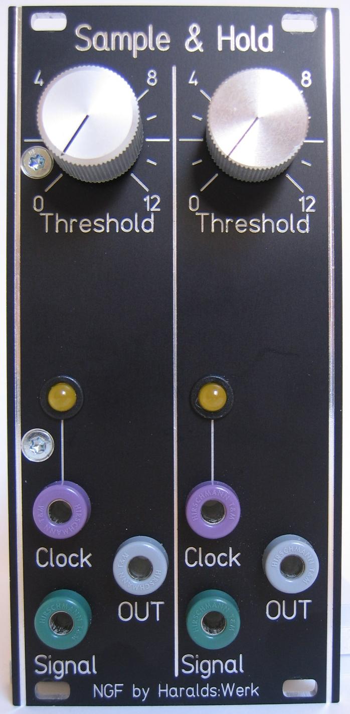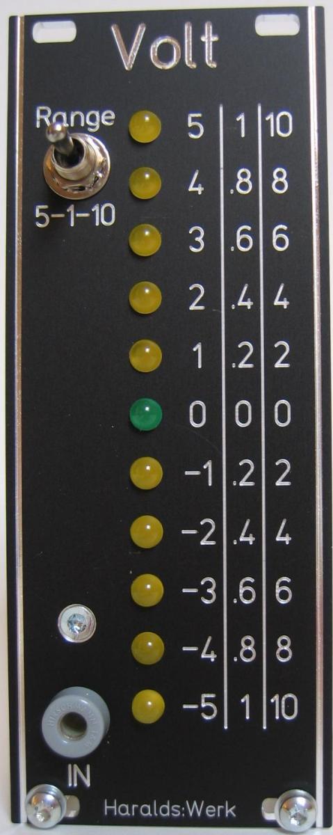
Voltmeter faceplate
The circuitry of this module was developed by Ray Wilson of MFOS. It was part of his Multi-Function Module. I have changed some resistor values to use with low current LED.
The LED voltage level meter gives you a graphical idea of where the voltage level you like to use to modulate your filter or VCA is. This circuit lights the LED in real time giving you a rough idea of the voltage level you are looking for. This is very useful when you want to move a CV from bipolar to only positive values.
Specs and features
• Three voltage ranges (+/-1V, +/-5V, +/-10V).
• Realtime LED display
• Runs on +/-15V and +/-12V
• Power consumption below 15mA each rail
The documentation for download can be found in my website.
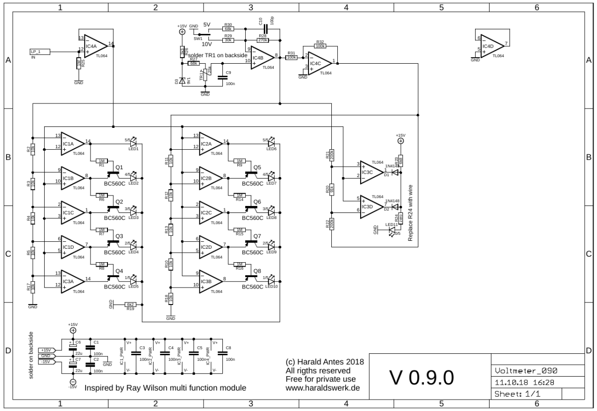
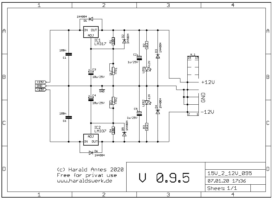
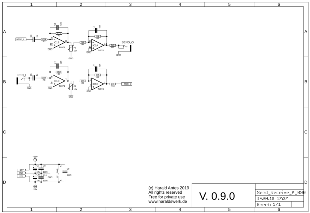
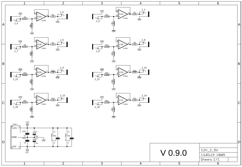
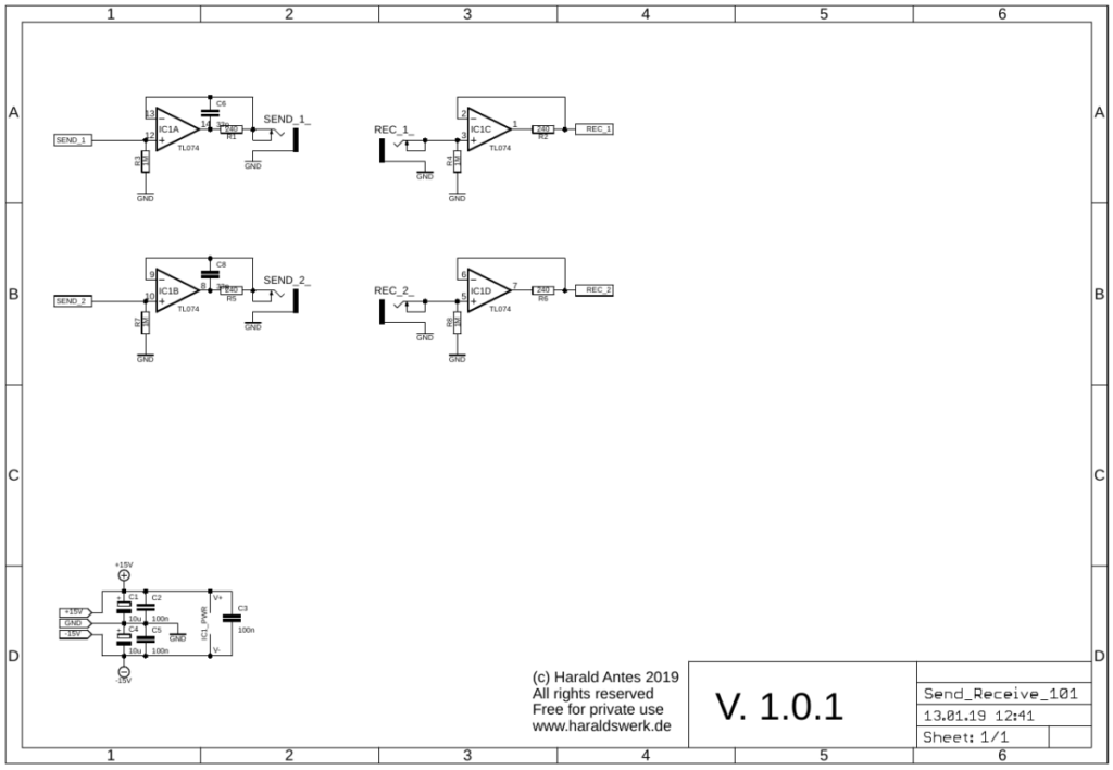
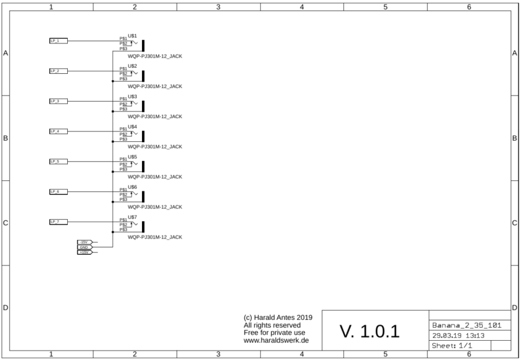
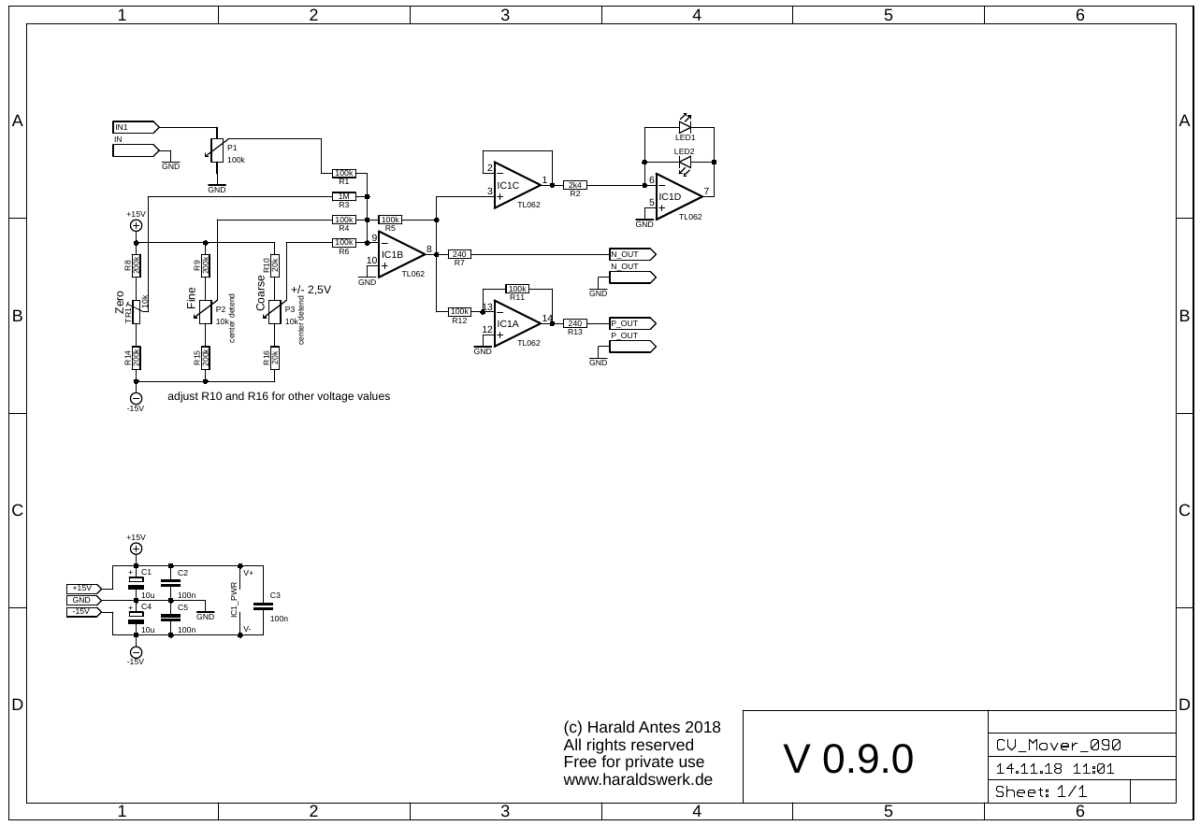
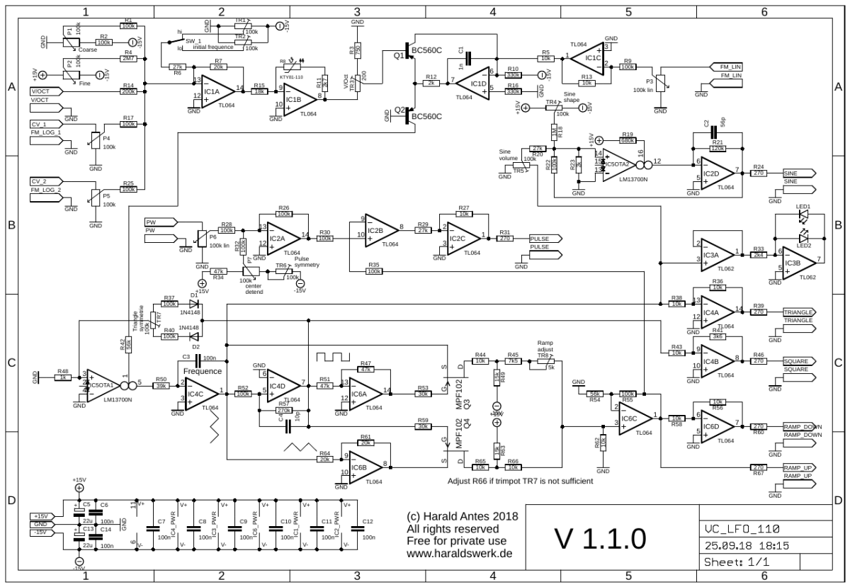
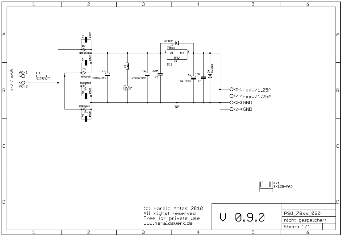
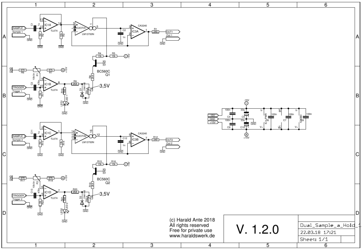
Voltmeter schematic
IC4A is used for input buffering. IC4B and IC4C and associated components build the range selection circuitry. The heart of the circuit is the group of comparators build with IC1x, IC2x, IC3A and IC3B. The left side is used to measure the positive voltage, the right side for the negative voltage. LED 11 is the “near ground” indicator. IC3C and IC3D build a window comparator. For a more detailed description please refer to the original source at Ray Wilson’s Site MFOS (Multi-Function Module).
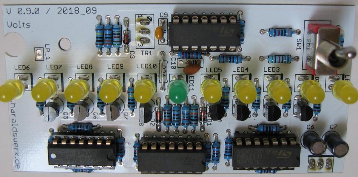
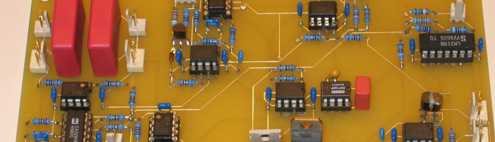
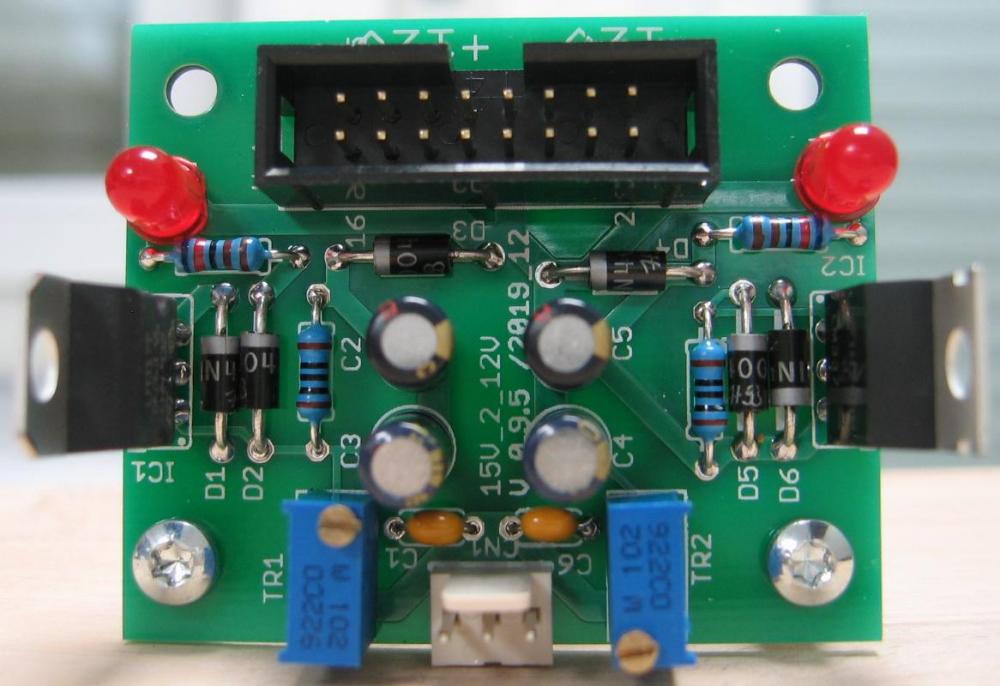
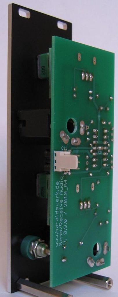
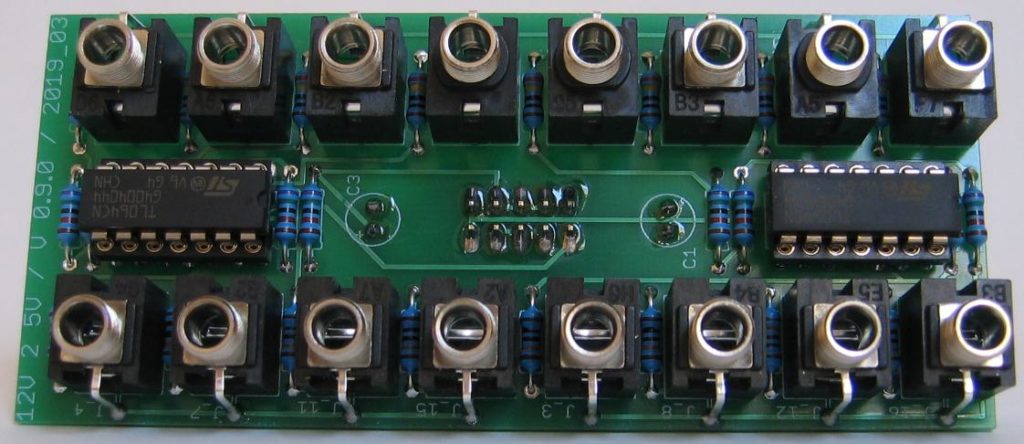
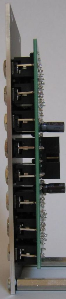
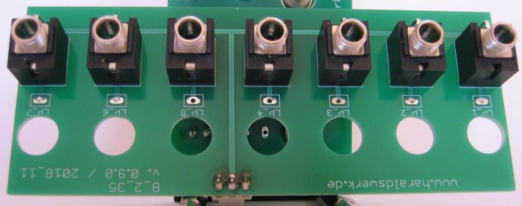
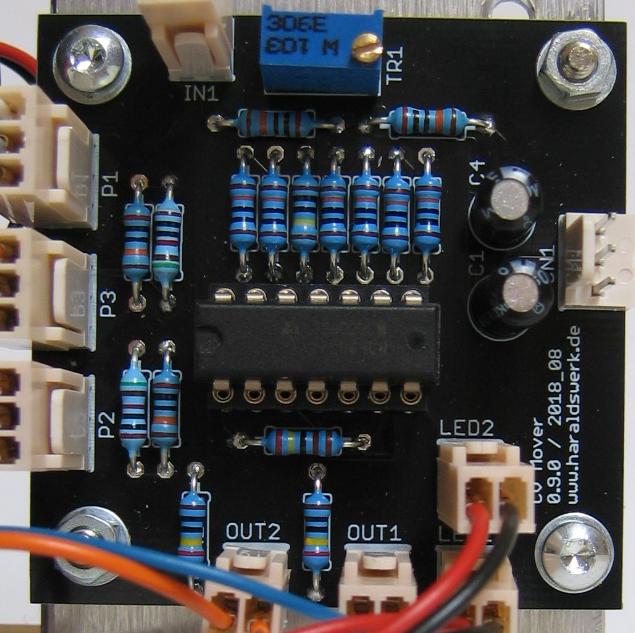
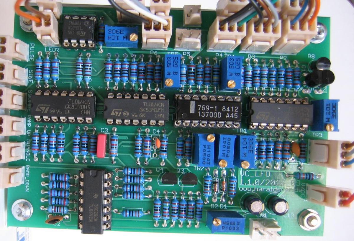
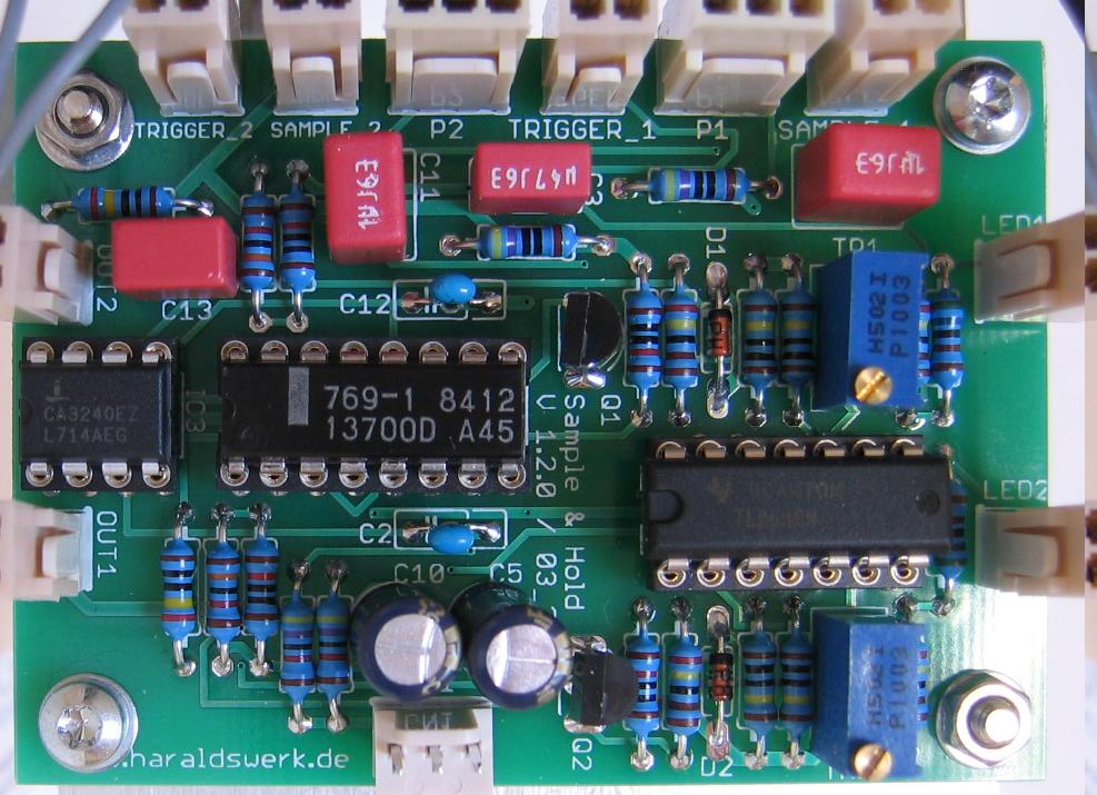
Voltmeter populated PCB
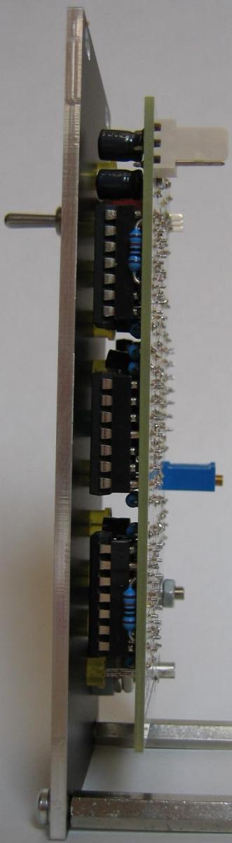
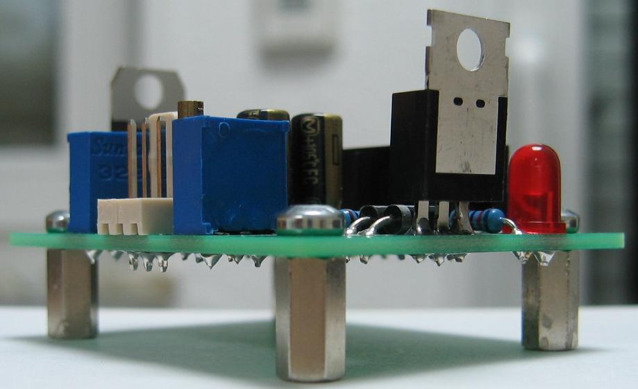
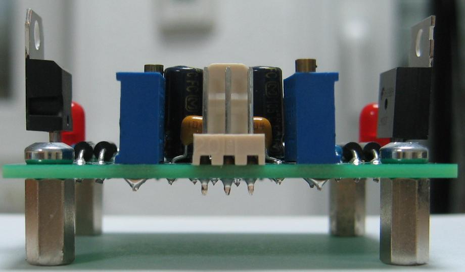
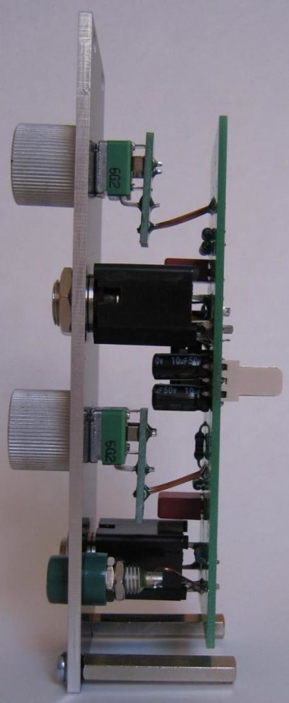
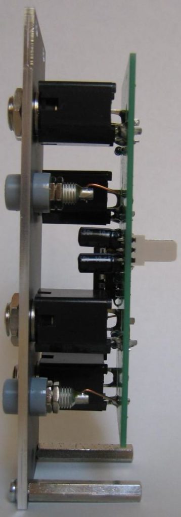
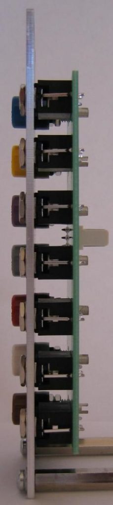
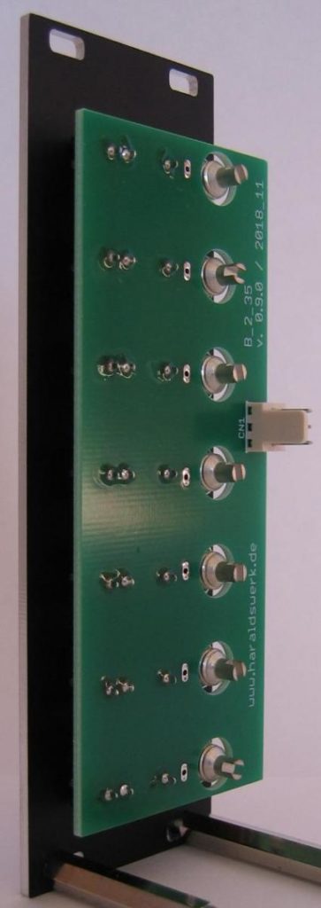
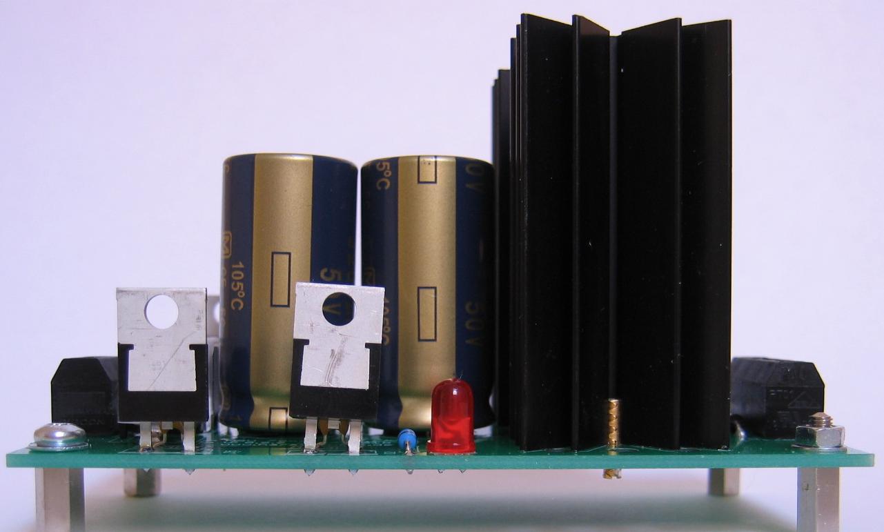
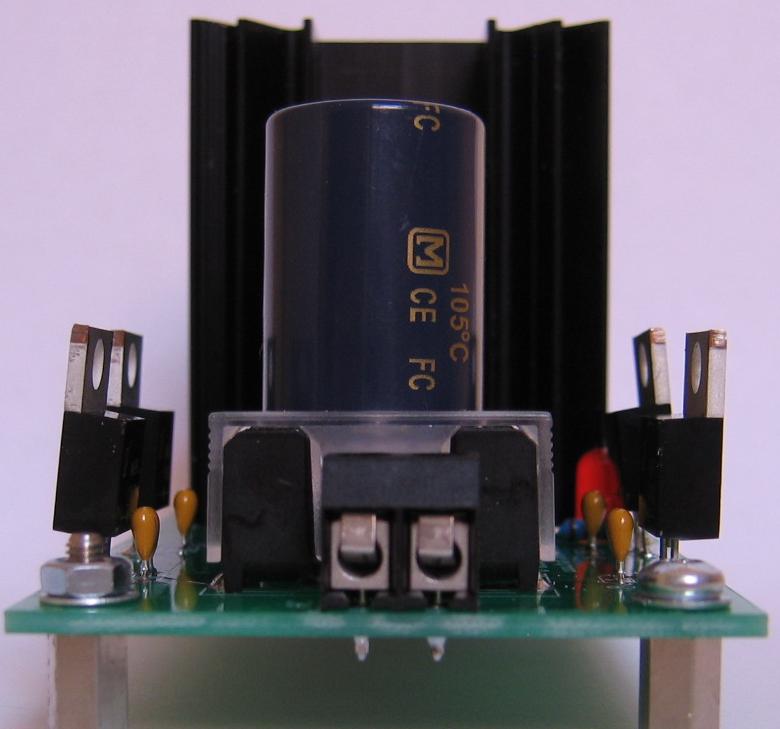
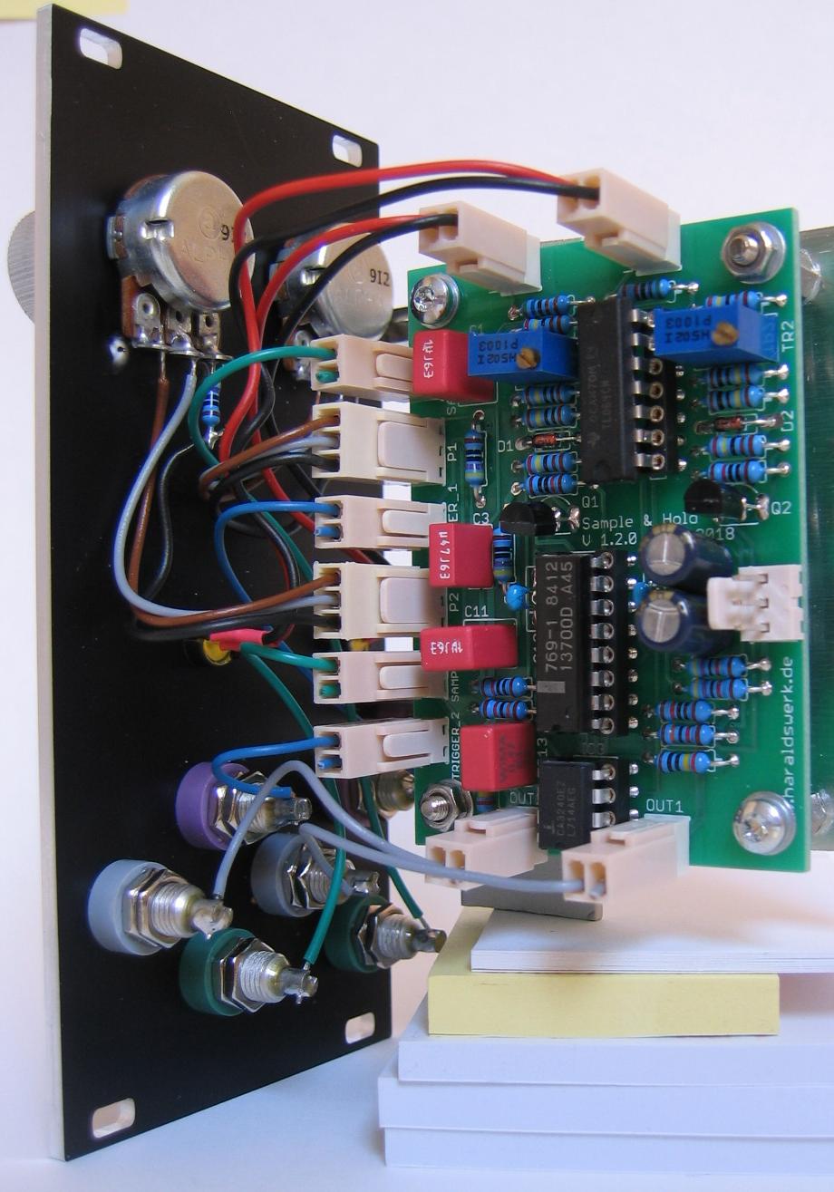
Voltmeter side view