NGF Project: Waveshaper

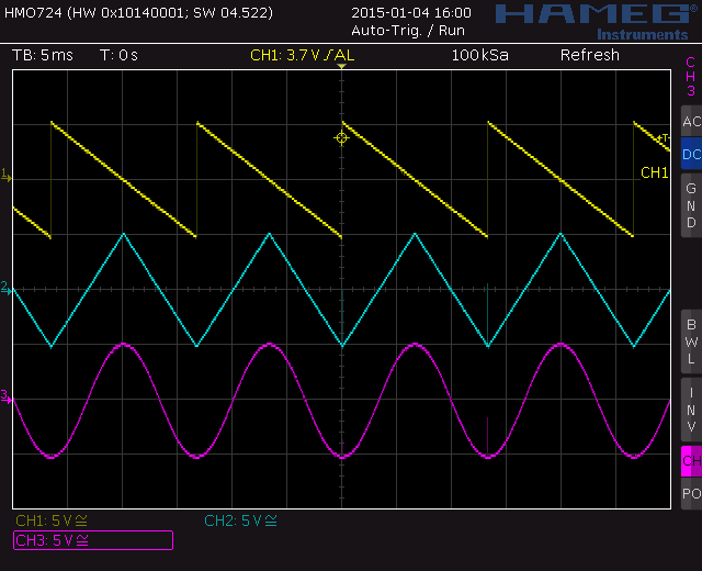
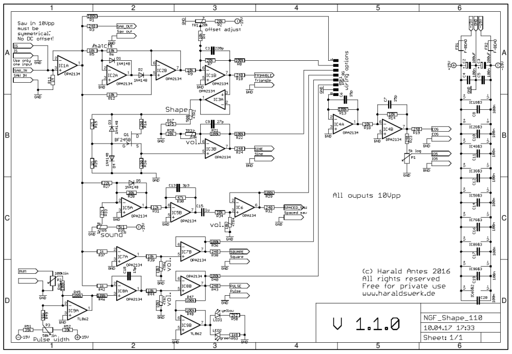
This is my waveshaper version for the NGF Project. It is basically the same schematic as for my waveshaper version 0.9.5 with an added output circuitry and wiring option to be used with a rotary switch or some SPST switches as in the original. I kept all the waveforms of the original Elektor Formant, but changed the circuitry significantly. The only thing i added is a symmetrical square out, that i found useful for sync. For converting the saw wave to triangle a precision full wave rectifier is used, followed by a level shifter. The originally used matched Germanium diodes are hard to obtain these days. Here you only have to match two resistors. The switching glitch is not audible and can be suppressed with means of a capacitor of some 100pF if wanted. Don’t choose the capacitance to high, it rounds the edge of the triangle. For triangle to sine conversion i used a well known circuit that works better then the two diodes approach from the original Elektor Formant. This circuitry can be found at various places in Electronotes and others. The circuitry is very sensible to the used resistor values and input voltage. The resistor values are done for a BF245B. BF245A or C will not work. If you use another input voltage you probably have to change type of FET and resistor values. For wave shaping from saw to spaced saw I kept the original circuitry from the Elektor Formant. I only have to change some resistor values due to the different signal level. New added is the saw to square waveshaper because I found it useful to have a symmetrical square output. The saw to pulse shaping is quite different to the original but quite standard.

The documentation for download can be found on my website.

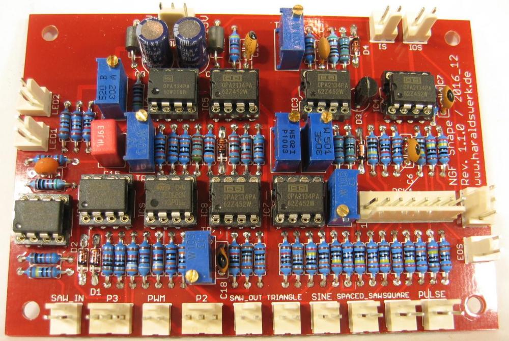
NGF Project: Waveshaper stuffed PCB

NGF Project: Waveshaper stuffed PCB

NGF Project: Waveshaper schematic

NGF Project: Waveshaper schematic

NGF Project: Waveshaper output saw, square and spaced saw

NGF Project: Waveshaper output saw, square and spaced saw

NGF Project: Waveshaper output saw, triangle and sine

NGF Project: Waveshaper output saw, triangle and sine

NGF Project: NGF VCO Core two

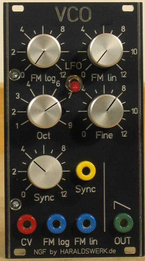
NGF VCO core two faceplate

NGF VCO core two faceplate

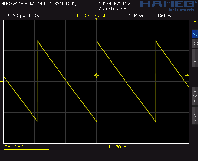
I have build my first original Elektor Formant VCO’s in the 70’s. They worked quite well and do so until today. Over the years i did implement some changes and extensions. I have developed a PCB Version with my changes and extensions published as VCO Core one. But only for those few lucky ones with some spare uA726. Here is the second VCO for my Next Generation Formant project. As in the NGF VCO core one I tried to keep the basic architecture of the original Elektor Formant. With the goal using only today available parts. This means finding a heated transistor pair for the expo converter and a Schmitt Trigger with hysteresis for the switching. Because there are no heated transistor pairs obtainable in the market today I was on my own. There are some solutions for a heated expo pair out there. Most of them build around no longer available parts or quite expensive. A still easy to get and cheap part is the LM3046. The SMD version is still in production today (2017 March) and the DIL version is easy to source as well. Though not longer in production. The PCB for the NGF VCO core two holds both versions. You can stuff it with the SMD- or DIL version. The 4093 is used as Schmitt Trigger for switching. Using the 4093 makes some level shifting necessary for proper switching. The switching capacitor is reduced to 470pF which give an even more better volt per octave characteristic then the original over the audio range. A LFO option is implemented as well. In conjunction with the waveshaper you have now the same waveforms available as voltage controlled LFO.The uA726 is replaced with LM3046 and the 7413 with 4093. All internal control voltages are stabilized. I removed the need for the +5V current supply, added an octave switch, FM lin and sync in. A new feature is the LFO switch. The signal level is raised to 10Vpp to get a better SNR throughout the system.

The documentation is available for download on my website.
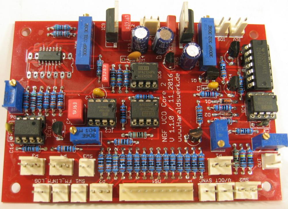
VCO Core two: stuffed PCB
VCO Core two: stuffed PCB

VCO core two saw out

VCO core two saw out

All changes I have made to my original Elektor Formant VCO are implemented: No extra 5V source is needed, all control voltages are stabilized, Octave switch, FM lin, 10Vpp output. New LFO option.
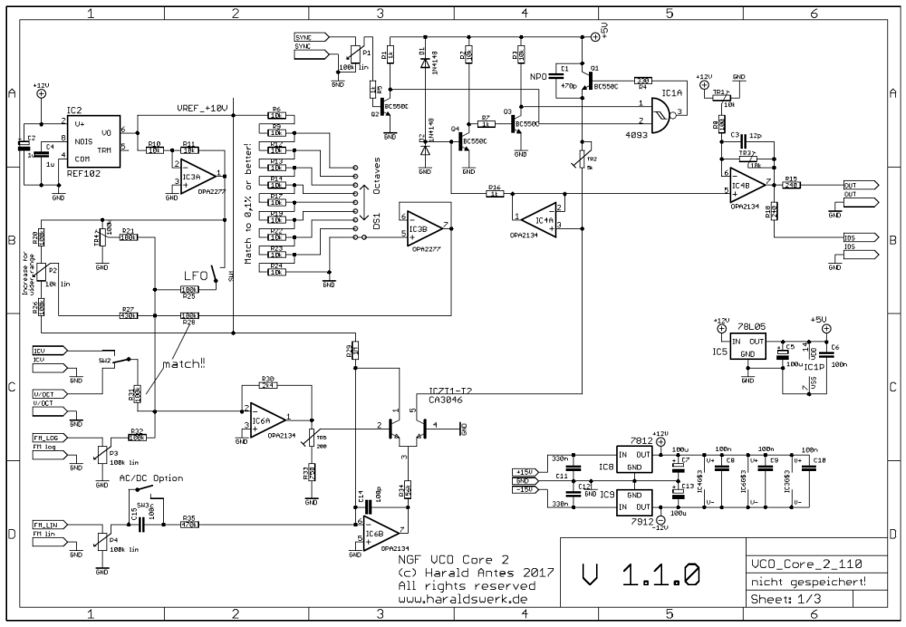
NGF VCO core two schematic

NGF VCO core two schematic

To keep the characteristic of the original Elektor Formant I kept the heated exponential converter, here build around the LM3046. The PCB is developed to hold the DIL and the SOIC version as well. The Schmitt Trigger used is the 4093. Due to different switching levels in the original some transistors are added for level shifting. The octave switch is build with the OPA2277 and the voltage reference REF102. Switch SW1 turns the LFO option on and off. The level for the Sync input is adjusted with P1. Fine tune of the pitch is done with P2. If you need a wider range for the tuning you can change it with changing the potentiometer or the resistors values here. The basic pitch is set with TR4. Output voltage is set with TR3 and the DC offset with TR1.
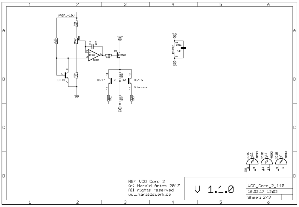
NGF VCO core two schematic heater

NGF VCO core two schematic heater

This circuitry is part of my NGF VCO Core 2. It make use of two transistors to heat the LM3046. It works with the SMD and DIL Version as well. The given resistor values keep the current values and the power dissipation below the maximum ratings. T3 is used to measure the actual temperature. The voltage drop over T3 is direct proportional to the chip temperature. It is compared to the voltage at pin 2 of the LM3046 which is derived from TR6. The temperature is easily adjusted with TR6. Between heating off and maximum temperature. The testing bridge is driven with a stabilized 10V voltage source. T4 and T5 are used as heaters. R41 and R43 limit the maximum current. The different values are selected with purpose to keep pin 13 of the LM3046 (the substrate) the lowest negative point at the chip.
 

Next Generation Formant Project: Housing and PSU

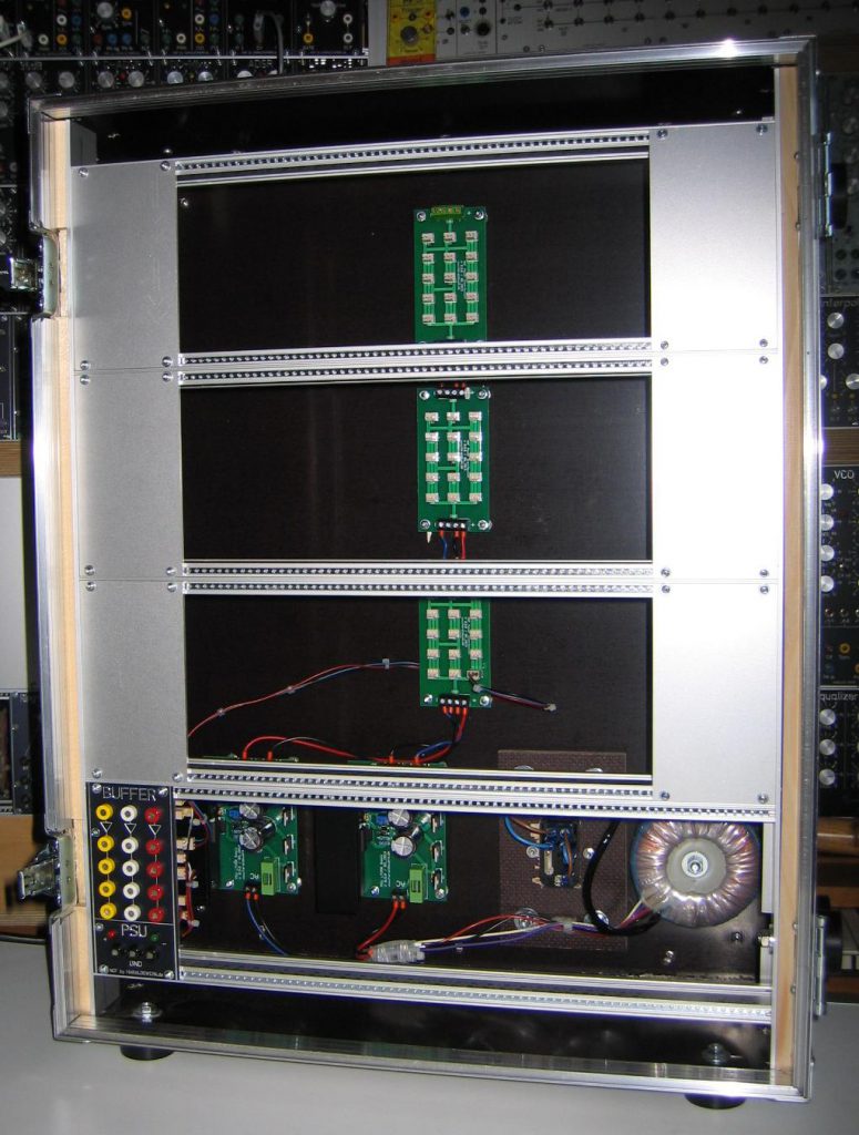
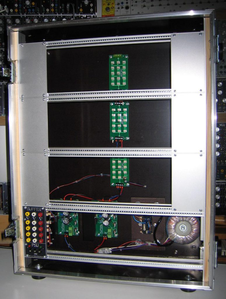
First step of the Next Generation Formant Project is the housing and the PSU. I want my Elektor Formant based clone to be portable. Therefore I ordered a custom made 19’’ flightcase, build to my specifications. The enclosure holds four rows of modules in Eurorack format. As PSU two of my basic PSU with LM350 are used.

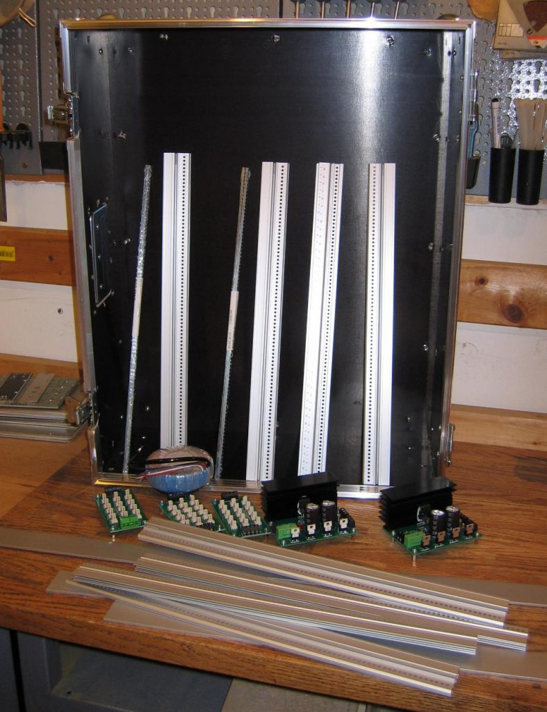
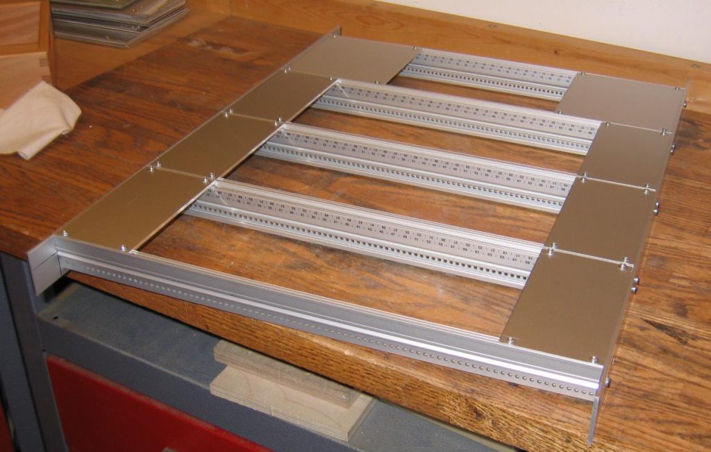
The first picture shows the enclosure, the rails and the PSU used. The lid is not shown.

Next Generation Formant Housing

Next Generation Formant Housing

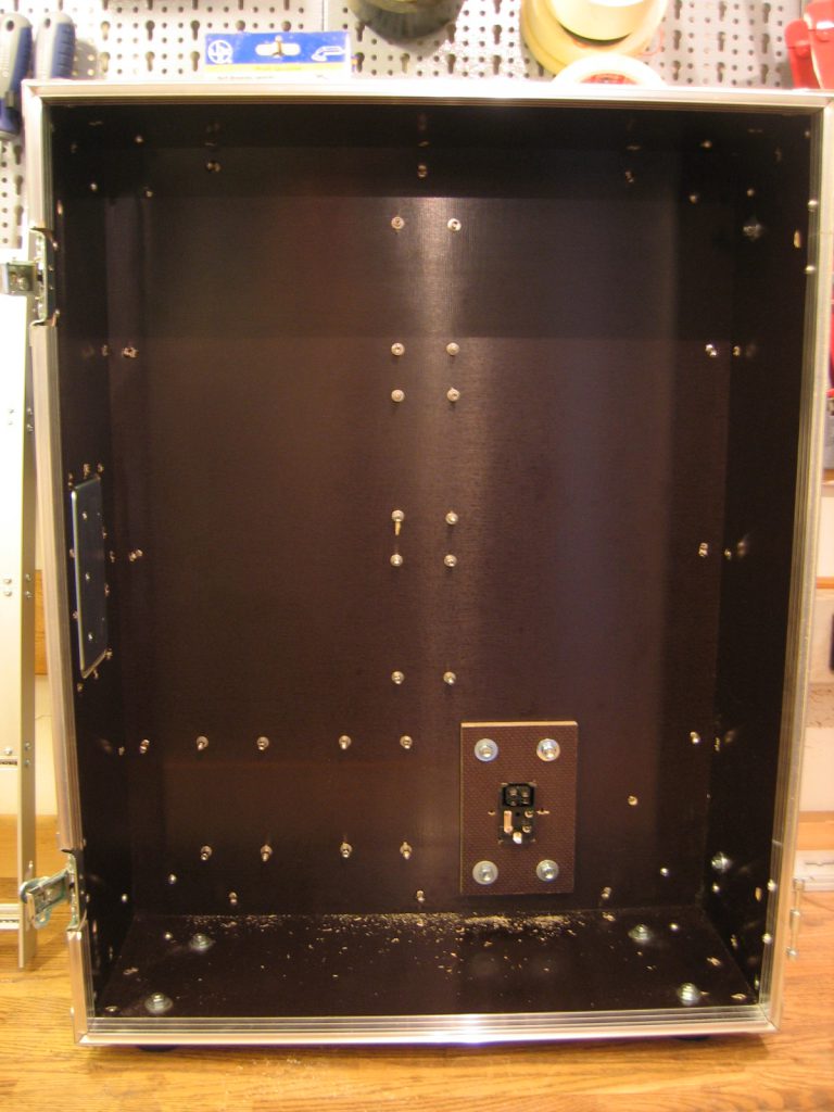
The first step was mounting the stand offs for the PSU and power distribution. The hole for the mains connecter and switch was cut out and the mains connector mounted.

Next Generation Formant Housing: Enclosure

Next Generation Formant Housing: Enclosure

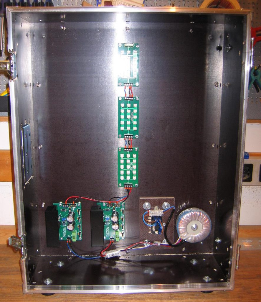
Next was to install the power supply unit, the power distribution and the mains transformer. The wiring was done and tested.

Next Generation Formant Housing: PSU mounted

Next Generation Formant Housing: PSU mounted

The frame to hold the modules is build from 19’’ rails. The sides are plain aluminum stripes.

Next Generation Formant Housing: Frame

Next Generation Formant Housing: Frame

The frame is mounted in the enclosure, the first module attached. The enclosure is ready for more.

Next Generation Formant Housing: Ready for modules

Next Generation Formant Housing: Ready for modules

Building Block: 3046 Heater

For my Next Generation Formant project i needed a replacement for the obsolete uA726, because i wanted to stay as close as possible to the original Elektor Formant VCO with my NGF VCO Core 2. This means a heated exponential matched transistor pair. There are a variety of possibilities to achieve this goal. Most of those solutions uses now obsolete parts or are hard to build. But there is still on well known solution with with the 3046 transistor array. And best, it is still available. At least the SMD Version is still in production. The DIL version can be found as well, but is no longer in production.

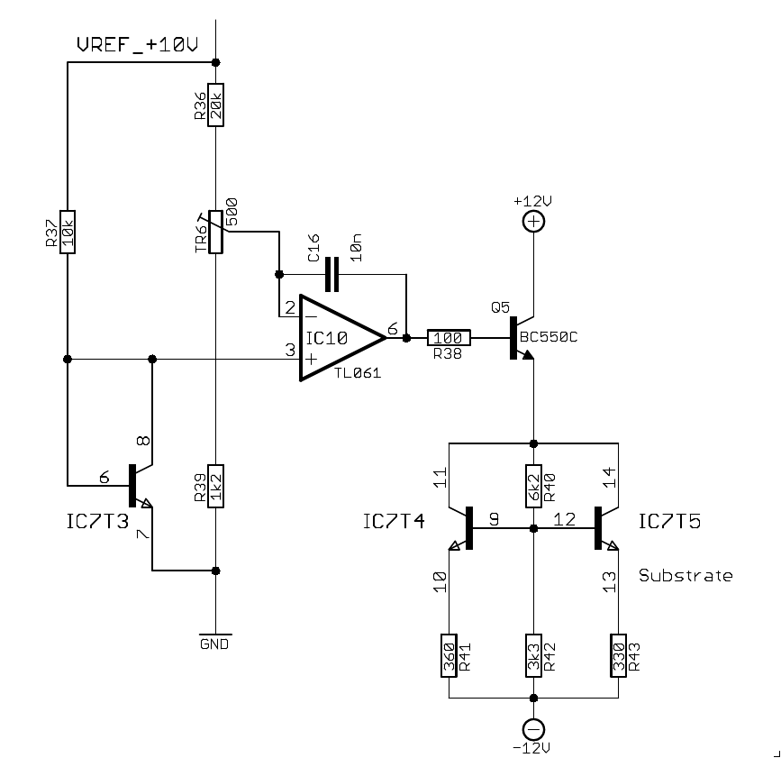
The circuitry I found on the net did only use one transistor for the heating. This leaves one transistor unused. My thought is using two transistors makes for a faster heating up and more stability against environmental change. To my surprise I can not find a solution which uses two transistors instead of one. Here is my take on the circuitry.

3046 heater schematic

3046 heater schematic

This circuitry is part of my NGF VCO Core 2. It make use of two transistors to heat the 3046. It works with the SMD and DIL Version as well. The given resistor values keep the current values and the power dissipation below the maximum ratings. T3 is used to measure the actual temperature. The voltage drop over T3 is direct proportional to the chip temperature. It is compared to the voltage at pin 2 of the 3046 which is derived from TR6. The temperature is easily adjusted with TR6. Between heating off and maximum temperature. The testing bridge is driven with a stabilized 10V voltage source. T4 and T5 are used as heaters. R41 and R43 limit the maximum current. The different values are selected with purpose to keep pin 13 of the 3046 (the substrate) the lowest negative point at the chip.
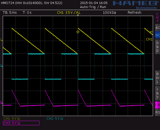
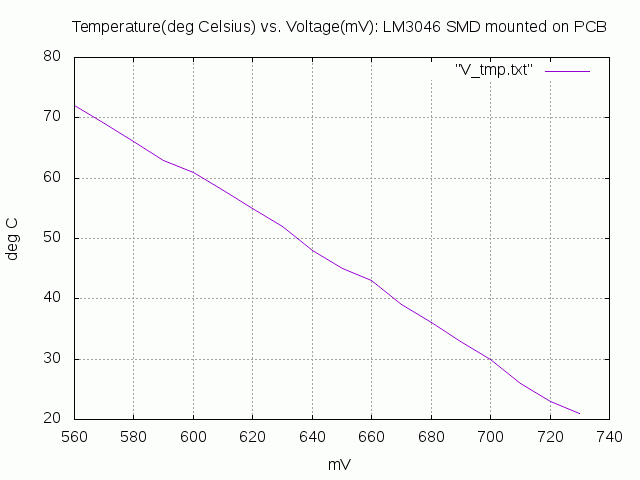
The below picture shows the graph temperature in deg. Celsius vs. Voltage in mV at pin2. It is quite linear. You can easily derive the needed voltage for your preferred temperature from the graph. The data were taken from a LM3046 SMD mounted on a PCB. The figures for the DIL Version are slightly different. They will show up on my website as well as some more details ASAP. Temperature was measured with Fluke 63 IR thermometer.

3046 heater: temperature vs. voltage plot

3046 heater: temperature vs. voltage plot

Next Generation Formant: Small project outline

I have build my first synthesizer end off the 70’s out of a kit which was based on the schematics from Elektor, a German DIY electronics magazine. This synthesizer was called “Elektor Formant”. This was way before the Internet gave us access to so many resources. Nearly everything has to be ordered via mail order. Or bought in shops if you was lucky enough to life nearby. The only resources then were some magazines or rare books. While life went on the building stopped. The synthesizer was stored away in a closet.

Some five years ago I started to restore my original Elektor Formant and got it working. Over the last years I build a lot of more modules from other sources first on strip-board and now on PCB. Mostly my own designs inspired by many fellow SDIY builders. I have done some bigger projects like Shakuhachi to Synthesizer which enables the Shakuhachi player to steer the synthesizer from the flute, or a 24 Band Vocoder.

Now it is time for another bigger project. Over the years I heavily modified my original Elektor Formant to enhance the performance, usability and add new features. This was done partly on the original Elektor Formant PCB or with additional circuitry on strip board. The additional functions leads to more knobs and plugs on the front panels. That means new face plates. And so on.

Finally I decided to build a complete new analog synthesizer to put all features and enhancements in it. All analog with PCB’s and today (end 2016) available parts, staying as close as possible to the original Elektor Formant. Here are the corner points:

  • Keeping all original features and the architecture
  • Front panel format 3HE
  • Audio Signal 10Vpp
  • CV and Audio interchangeable
  • Working on +/-15V and +/-12V as well
  • Gate +5V
  • All internal control voltages stabilized
  • PCB size max. 10x10mm
  • Portable housing

In the course of this project I will describe all changes that I made to the original Elektor Formant as well. Those will show up in the Elektor Formant Mods section on my website. The Next Generation Formant project will have a dedicated website with the current state of all modules.

Tool: Transistor Matcher

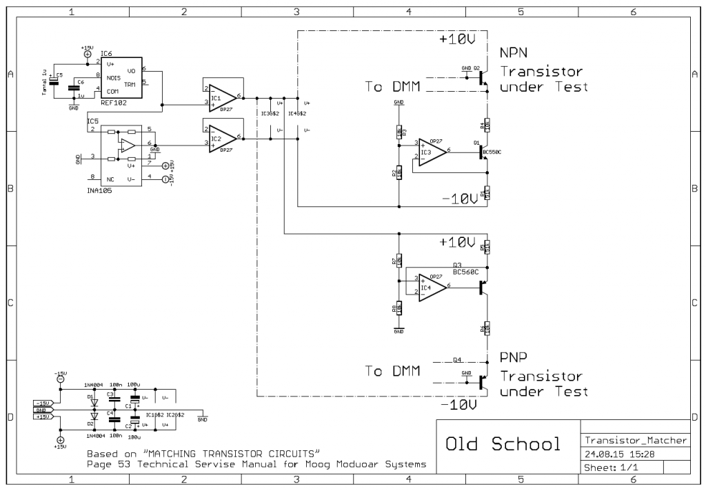
Matched transistor-pairs are often needed while building modules for synthesizers. Especially for exponentiators and differential amplifiers. Not to forget the Moog style ladder filters. I build an transistor matcher for me many years ago and still use it. I know that there are easier matching circuits out there today but mine works great for me so there is no need to change. Mine is based on the original transistor matcher found in the “Technical Service Manual for Moog Modular Systems” on page 53. I added some circuitry for stabilizing the used voltages. That was done to be able to repeat the measurement without bothering about the power supply adjustment. We are dealing with 1mV – 2mV here!

Transistor Matcher schematic

Transistor Matcher schematic


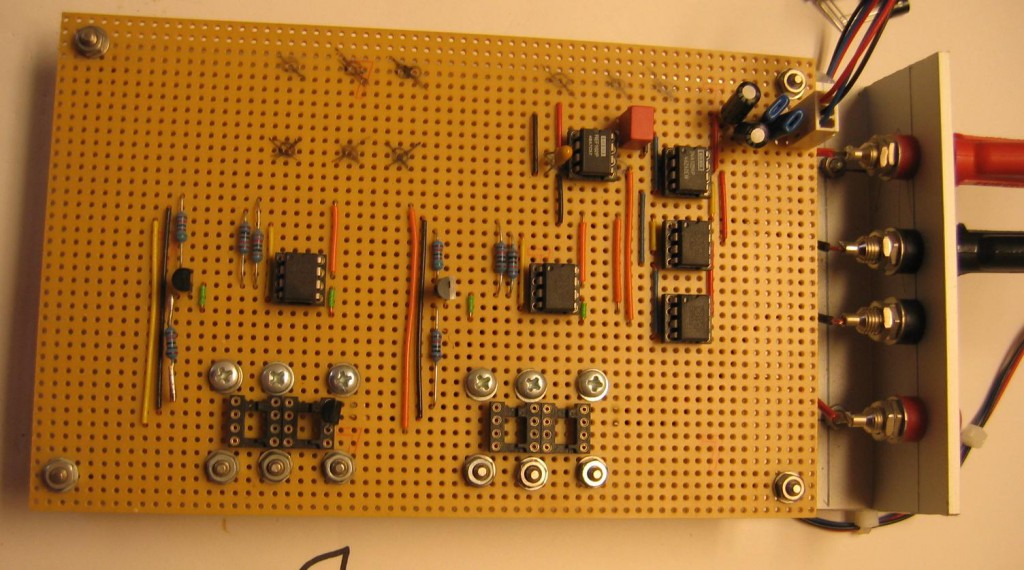
There was no need for a PCB. I just put it on perfboard and used IC sockets for the DUT.

Transistor Matcher

Transistor Matcher


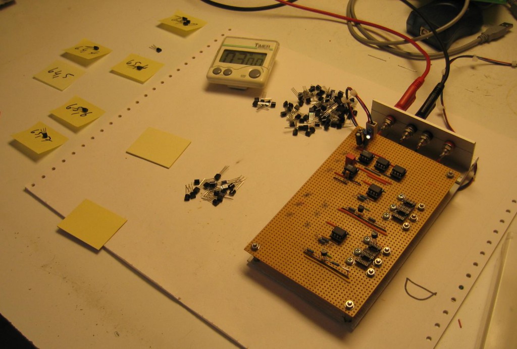
The usage is easy but you have to consider some precautions. The measurement is very temperature sensitive. You need to keep your environment stable. Use pliers to mount the DUT. Place the transistors into the socket. Measure base to emitter voltage. Don’t touch the transistors with fingers. The finger heat will cause the readings vary. Mark down the Vbe and find two transistors that the Vbe matches within 2mV or better.

Transistor Matcher usage

Transistor Matcher usage


With today standards of fabrication transistors it is not unusual to find nearly every transistor within the 2mV Vbe range in a batch. You can easily match your pairs to better standards. Depending on your equipment 0.5mV Vbe match should be easily to reach. But always remember: The measurement is very sensitive. Be careful with your setup!

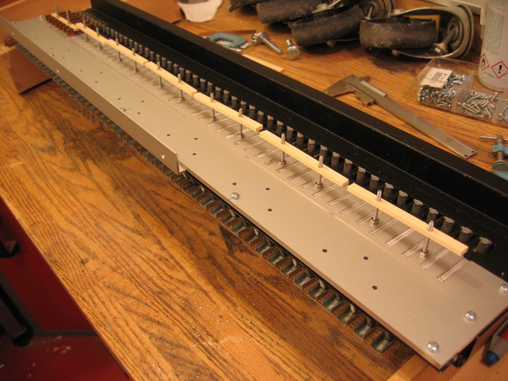
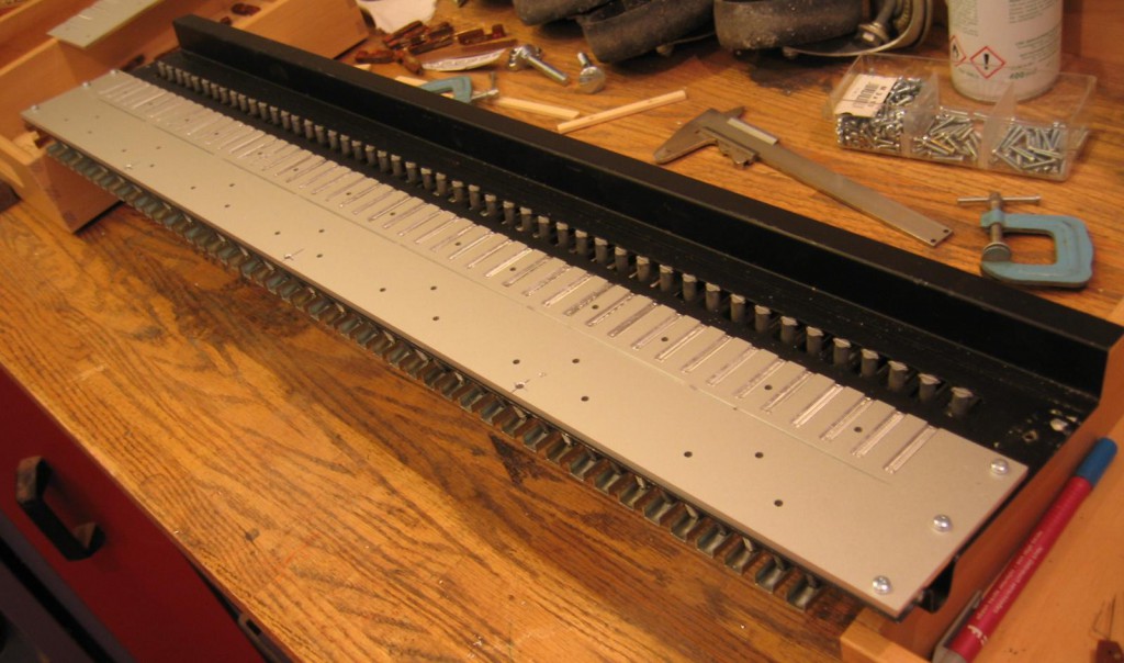
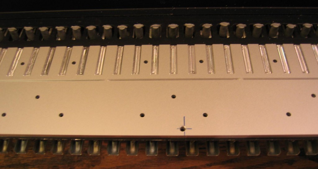
Scanning Keyboard: Mechanics IV – First wiring

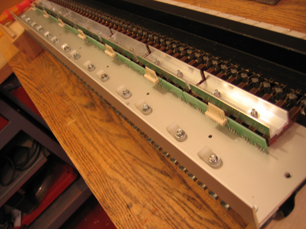
This is the last post about the mechanics. I promise. I have now a mechanical working keyboard with Kimber Allen contacts and the basic wiring. Next step are the electronics. I have them working since 2004 but it might be useful to do some rework with newer parts. I have to move from stripboard to PCB as well.

New holder waiting for contacts

New holder waiting for contacts

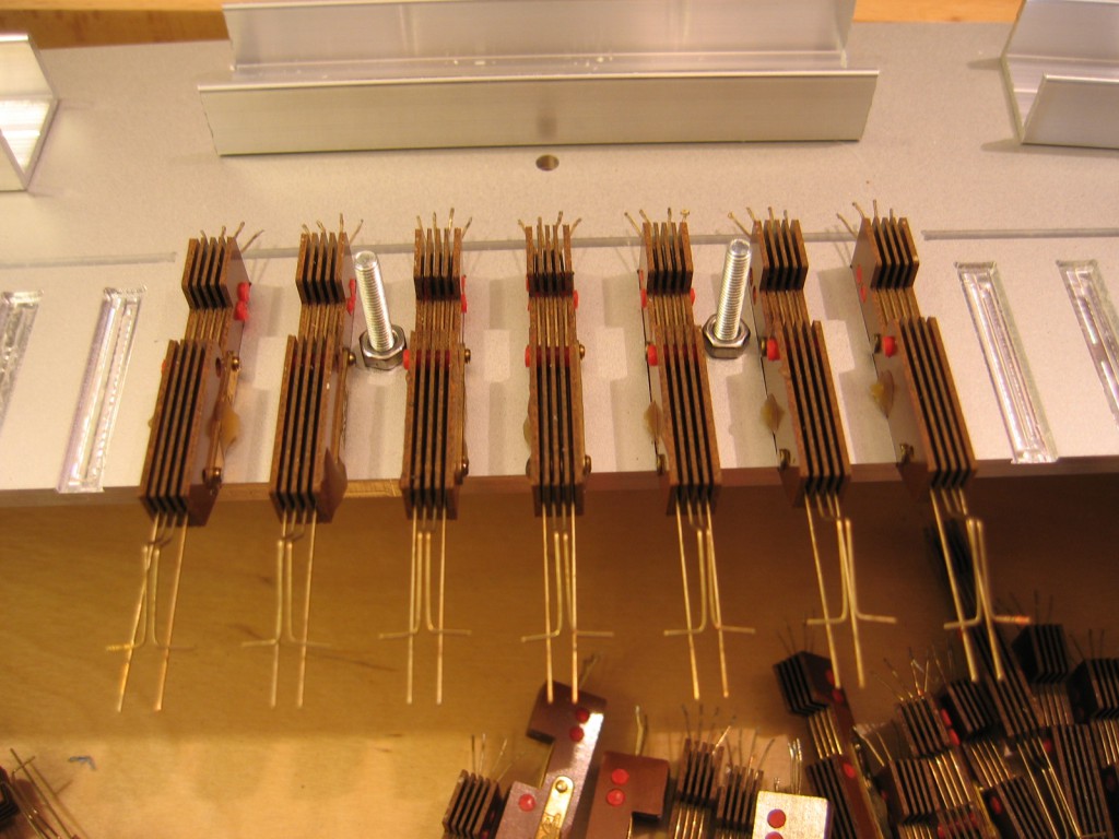
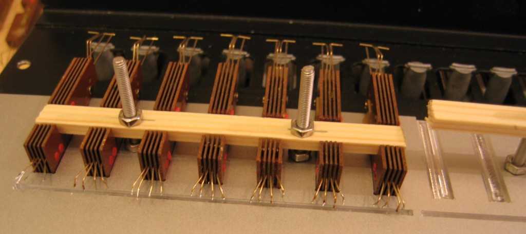
Fitting the contacts and do some rework if needed.

Fitting the Kimber Allen contacts

Fitting the Kimber Allen contacts

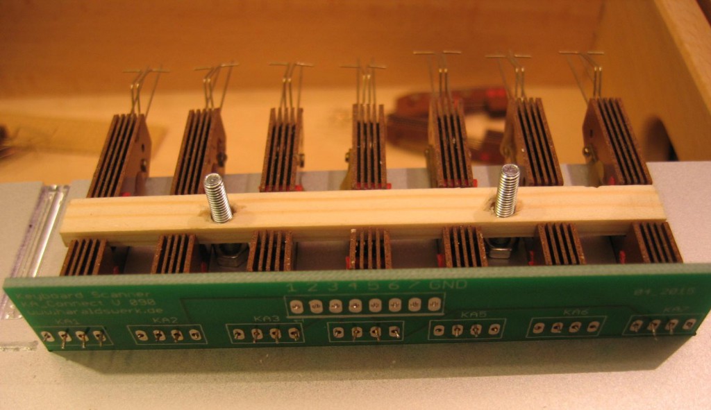
Fitted and mounted with PCB

Fitted and mounted with PCB

Fitted and mounted with PCB

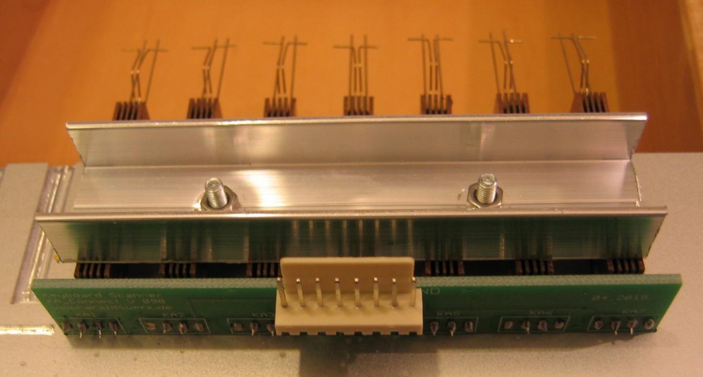
Soldered and screwed

Contacts soldered and screwed

Contacts soldered and screwed

Putting it together

Contacts mounted with keyboard action

Contacts mounted with keyboard action

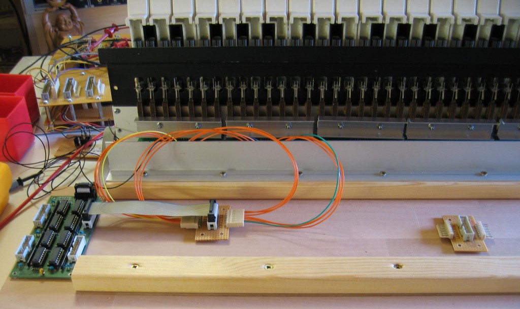
Some wires

First wiring to the shift register

First wiring to the shift register

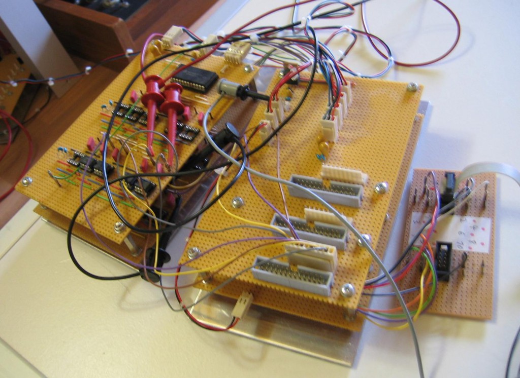
Old scanner electronics from 2004

Old scanner electronic

Old scanner electronic

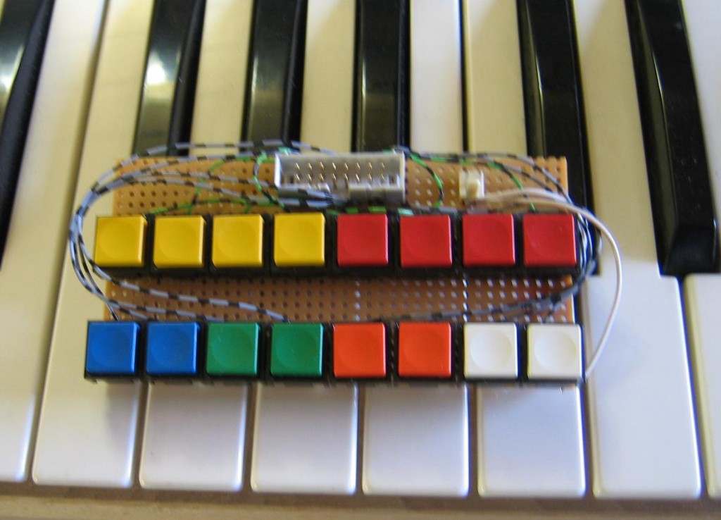
And my first “keyboard” from 2004

First test keyboard

First test keyboard

The new keyboard mechanic is working quite well with the old electronic. It is a lot of fun playing chords with the synthesizer. Next step is to think about the electronic. I want to get rid of the old stripboards and make some small PCB. Back then i used a ATmega8 and shift registers for keyboard scanning and a 16bit R2R ladder for DA conversion. Programmed in assembler. Maybe it is time to redo it in C and using a DA chip. I’ll give it a try.
NGF VCF 36dB: First steps

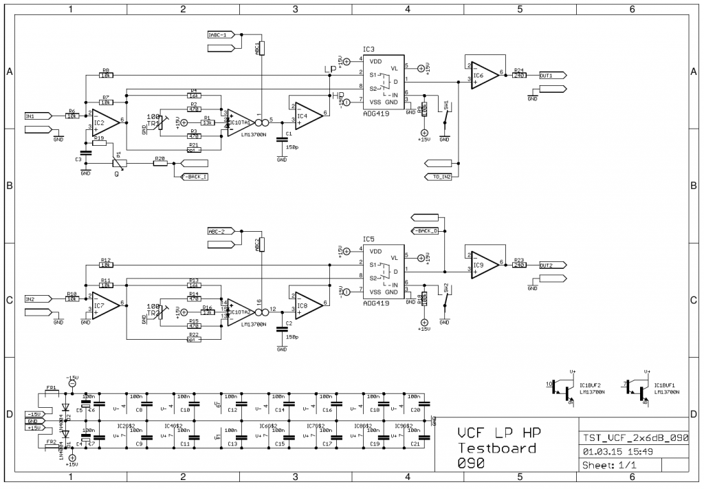
While waiting for the PCB’s to connect my Kimber Allen contacts to the electronics of the keyboard scanner I worked on my long planned 36dB VCF. I wanted a replacement and additional VCF for the original 24dB Elektor Formant filter. I kept the original structure and just added two more 6 dB filter cells. The emphasis (Q) is now voltage controlled. I added a linear timbre modulation and a “gender changer” for the ENV pot for better usage as well. And I replaced the mechanical LP/HP switch with electronic switch DG419. Maybe I am looking in 48dB next time not knowing if this makes sense musicaly.

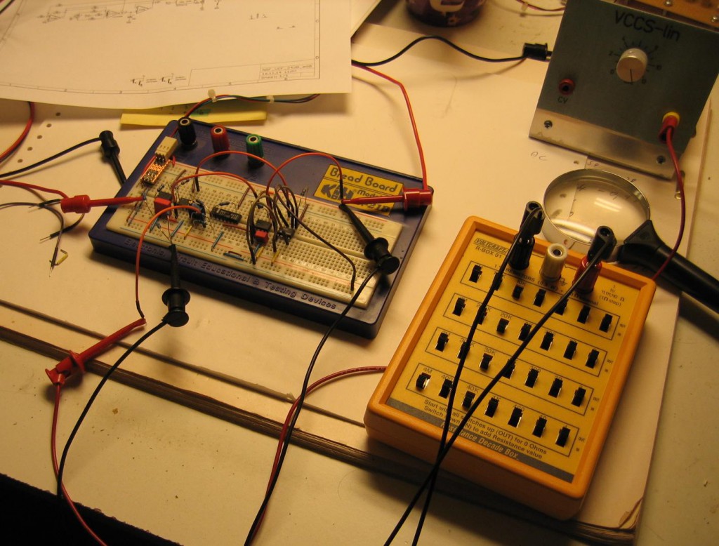
To start I tested one 6dB cell with one half or a LM13700 and the DG419 switch on breadboard.

VCF 6dB cell on breadboard

VCF 6dB cell on breadboard

Drawing the schematic:

VCF 2x6dB schematic

VCF 2x6dB schematic

Next was to make some PCB with two 6dB cells each.

VCF 2x6dB cell PCB

VCF 2x6dB cell PCB

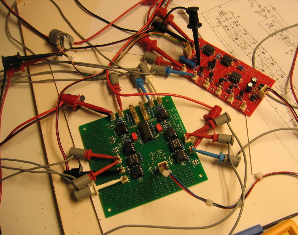
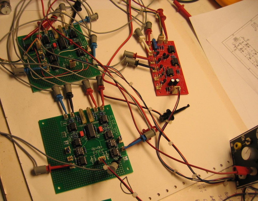
The red PCB on the picture is a prototype of a logarithmic voltage controlled current source with multiple outputs (Will come later in this blog). The green PCB is the filter. Those two 6dB cells makes quite a good 12dB VCF like the original 12dB Elektor Formant filter.

Adding two more for 24dB

VCF 24dB

VCF 24dB

Those four 6dB cells makes quite a good 24dB VCF like the original 24dB Elektor Formant filter.

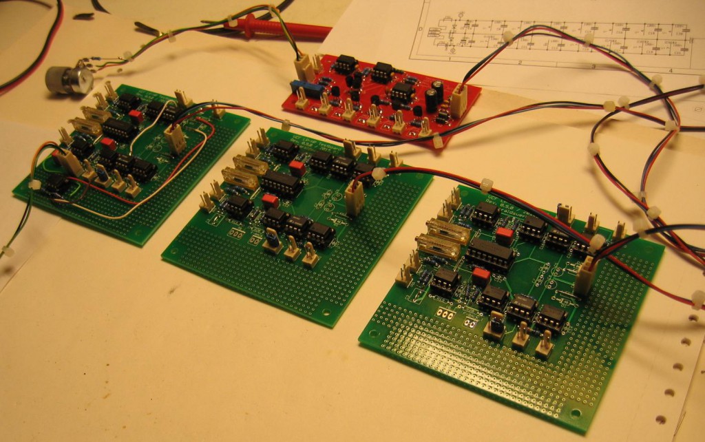
Adding two more for 36dB

VCF 36dB

VCF 36dB

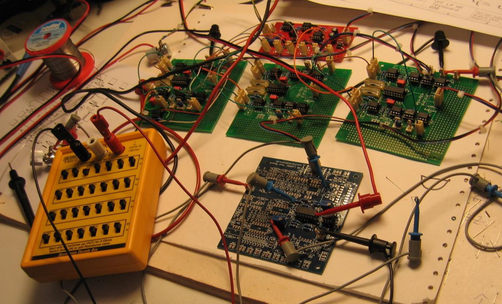
Putting it together and adding the voltage controlled feedback path(Q). The feedback path was added with means of the partly stuffed blue PCB. This one contains the prototype of my implementation of the Moog ladder filter, where I will use the same feedback technique (More in a later blogpost).

VCF 36dB with feedback

VCF 36dB with feedback