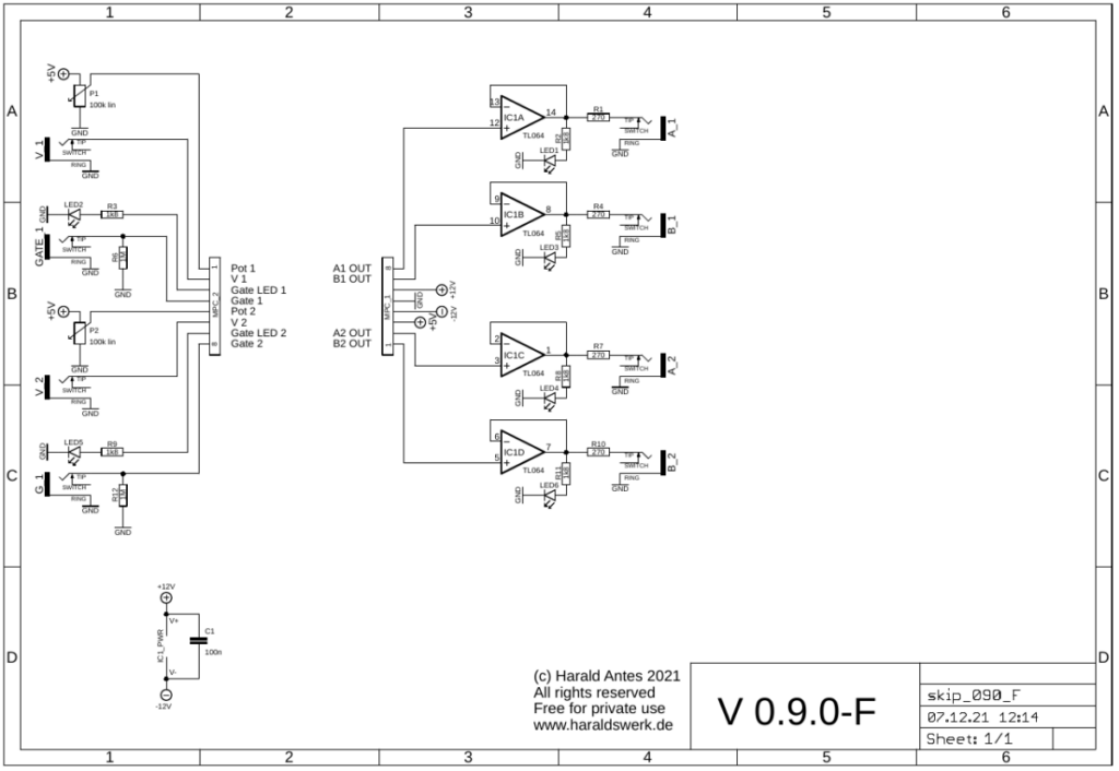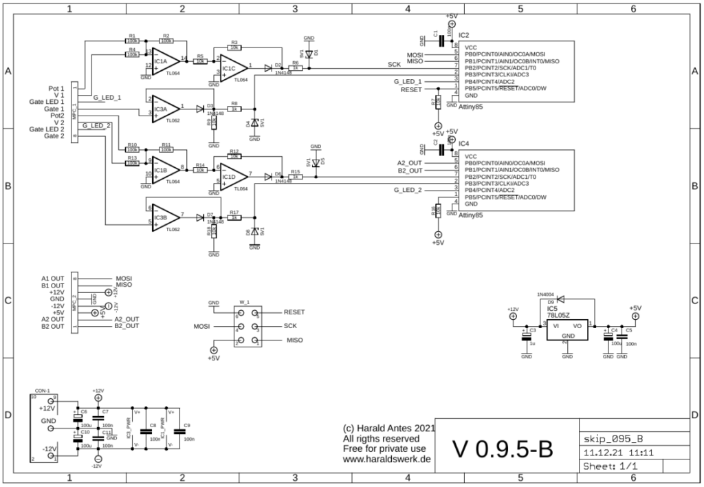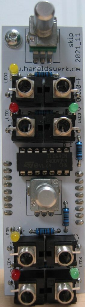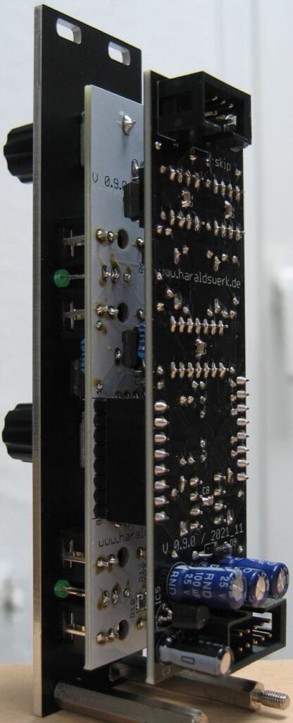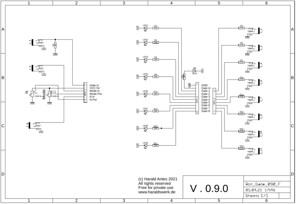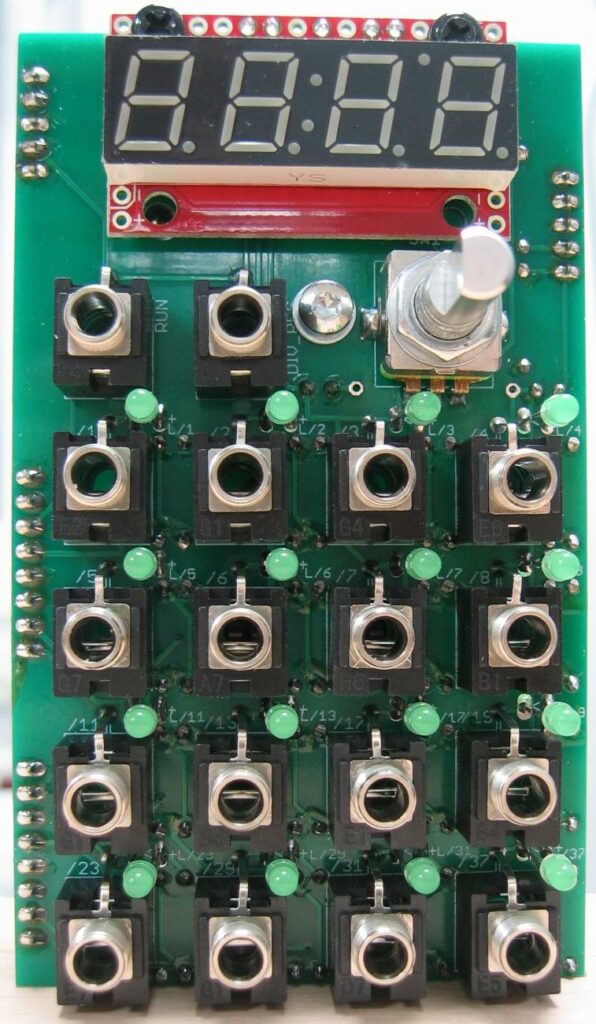
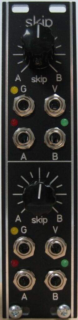
This module takes the incoming gate or trigger and routes it to either of its two outputs. The distribution is software driven, according to a random coin toss. You can select the probability distribution with a potentiometer and an input control voltage. The potentiometer voltage and the control voltage are added together. The probability goes from 0% to 100% at output A and from 100% to 0% on output B.
Specs and features
- Randomly skip Gates and Triggers
- Probability distribution voltage controlled
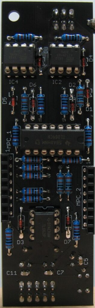
- Dual Bernoulli gate
- Runs on +/-12V and +/-15V
- Power consumption below 20mA positive rail. 5mA negative rail.
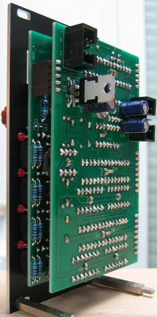
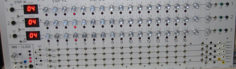
The documentation and the Gerber files for download can be found in my website.