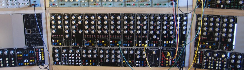
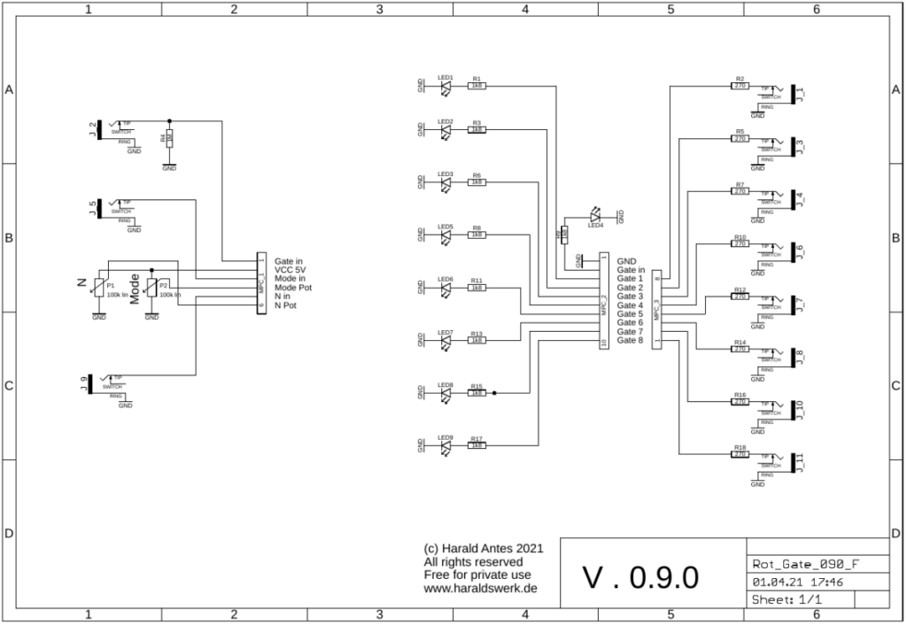
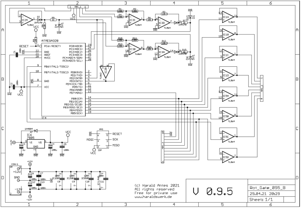
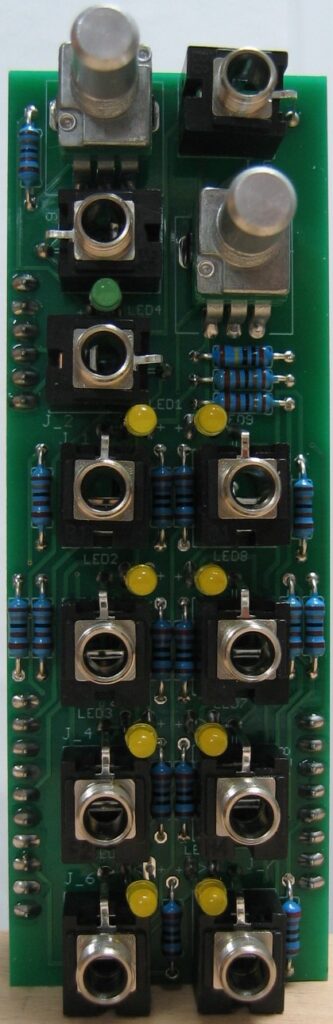
With this module you can distribute the incoming gate or trigger up to eight outputs. The distribution is software driven. You can select the amount of the used outputs from zero to eight with a potentiometer and an input control voltage. The potentiometer voltage and the control voltage are added together. The mode potentiometer and the mode control voltage selects the algorithm for the distribution. As for the moment (2021 Nov.) only one mode is implemented. Rotating upwards. Any suggestions or programs are welcome.
Specs and features
Gate/Trigger distribution up to eight targets.
Number of used outputs voltage controlled
Distribution algorithm voltage controlled
Runs on +/-12V and +/-15V
Power consumption below 20mA positive rail. 5mA negative rail.
The documentation and the Gerber files for download can be found in my website.
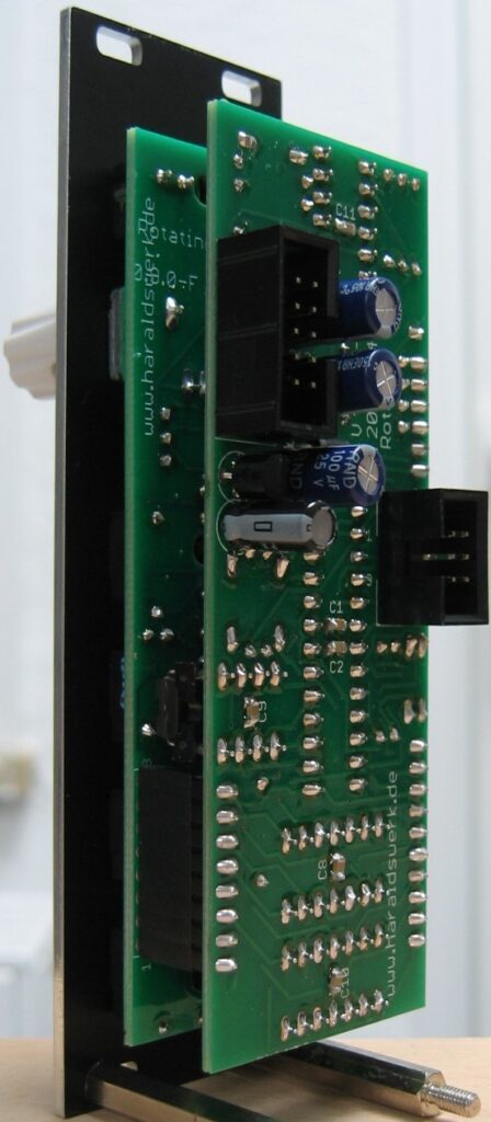
Rotating Gate: Schematic control boardRotating Gate: Schematic main boardRotating Gate: Populated control PCBRotating Gate: Populated main PCBRotating Gate: Back viewRotating Gate: Side view
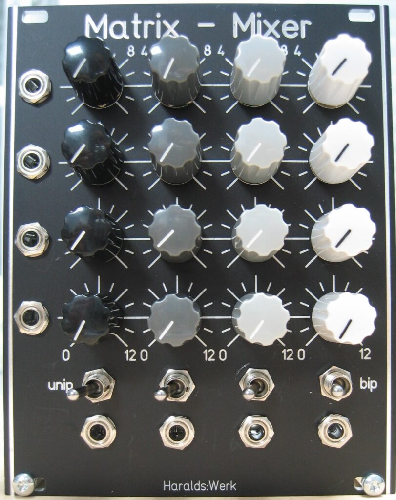
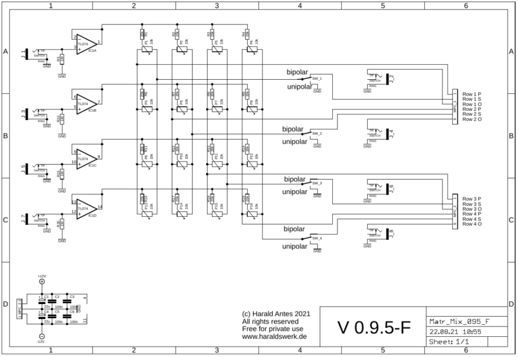
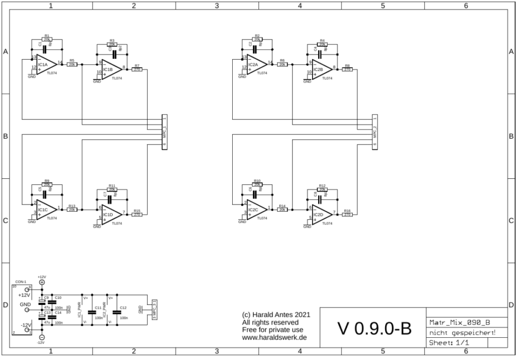
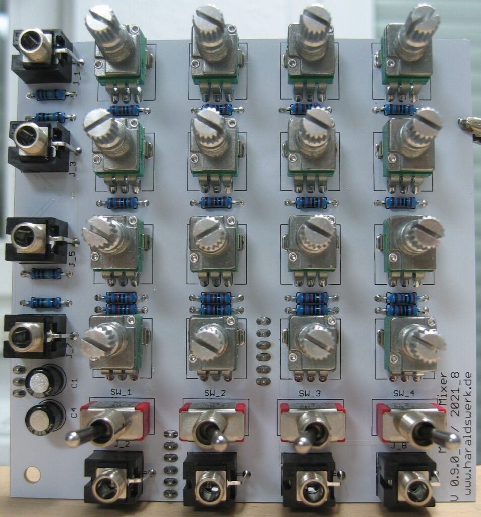
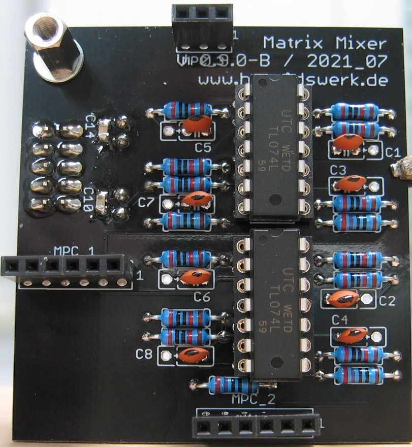
This is a 4 x 4 matrix mixer with switches for unipolar/bipolar mode for each column. Unipolar means that the controls work as attenuators. Bipolar means that the controls work as attenuverters. In this mode the amplification is zero in the middle position of the corresponding potentiometer. Turning the knob counterclockwise from the center position the signal is subtracted from the output sum. Turning the knob clockwise from the center position the signal is added to the output sum. The module is DC-coupled and can be used for audio and control voltage mixing.
Specs and features
4×4 Matrix
Switchable unipolar or bipolar mode
Power consumption below 30mA each rail
The documentation and the Gerber files for download can be found in my website.
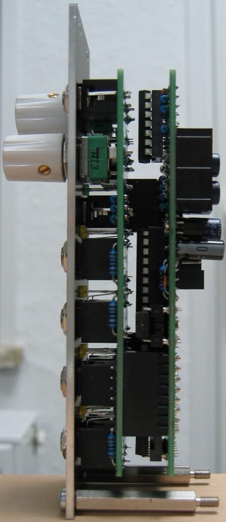
Matrix Mixer: Schematic control boardMatrix Mixer: Schematic main boardMatrix Mixer: Populated control PCBMatrix Mixer: Populated main PCBMatrix Mixer: Back viewMatrix Mixer: Side view
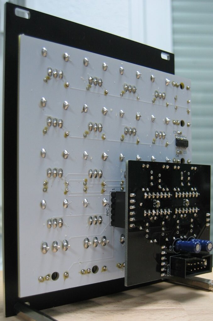
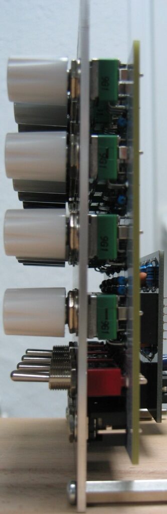
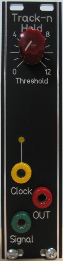
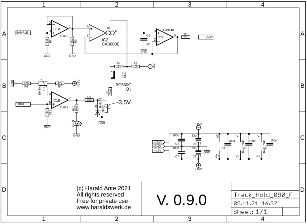
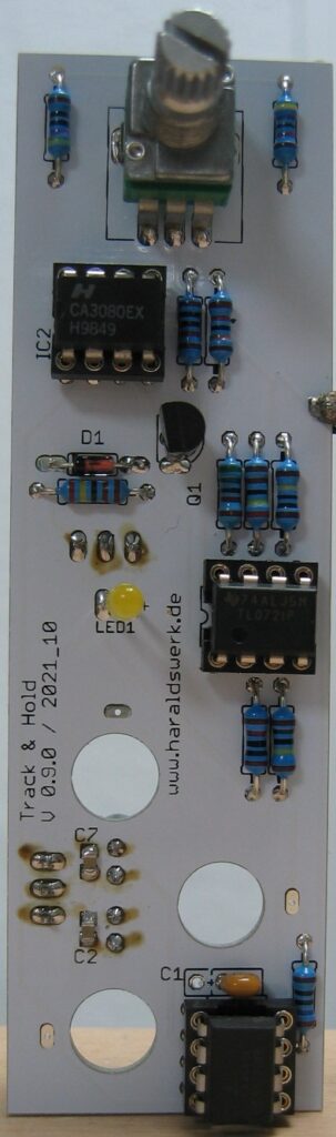
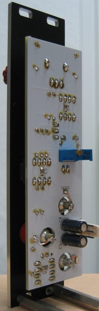
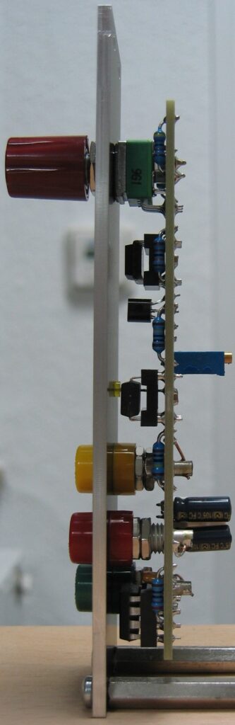
One more module for my Shakuhachi to Synths project. Not exclusively of course. This is a Track and Hold. Which is quite useful for other patches as well. In the Shakuhachi patch it is used to suppress an incomplete pitch to voltage conversion from the Pitch to voltage converter when the player stops blowing. The module tracks the incoming (control) voltage as long as the gate input is high. When the gate goes low the output voltage is kept. The module is DC coupled to track slowly moving voltages. For this one I have used some obsolete parts, which I had laying around. So, if you want to build it, make sure that you can get those parts. You can use it as Sample and Hold as well. Instead of a gate apply a trigger at the gate input.
Specs and features
Track or Sample and Hold
DC coupled
Gate input with LED
Signal input
Signal output
Threshold
Runs on +/-12V and +/-15V
Power consumption below 20mA each rail
The documentation and the Gerber files for download can be found in my website.
Track (Sample) and Hold: SchematicTrack (Sample) and Hold: Populated PCBTrack (Sample) and Hold: Back viewTrack (Sample) and Hold: Side view
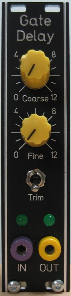
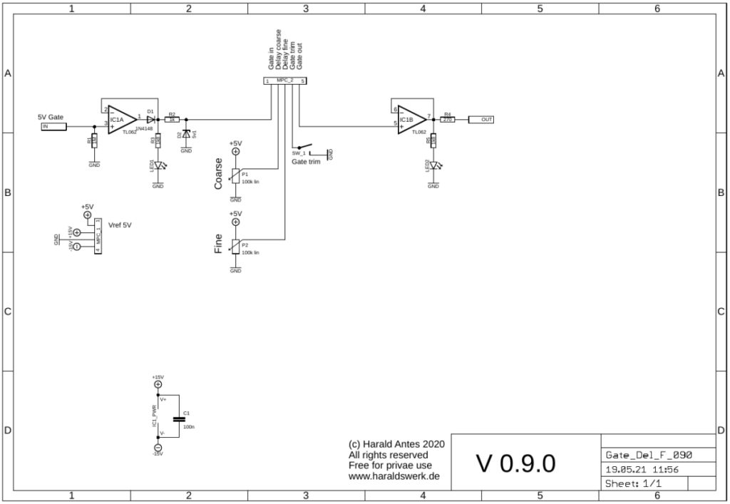
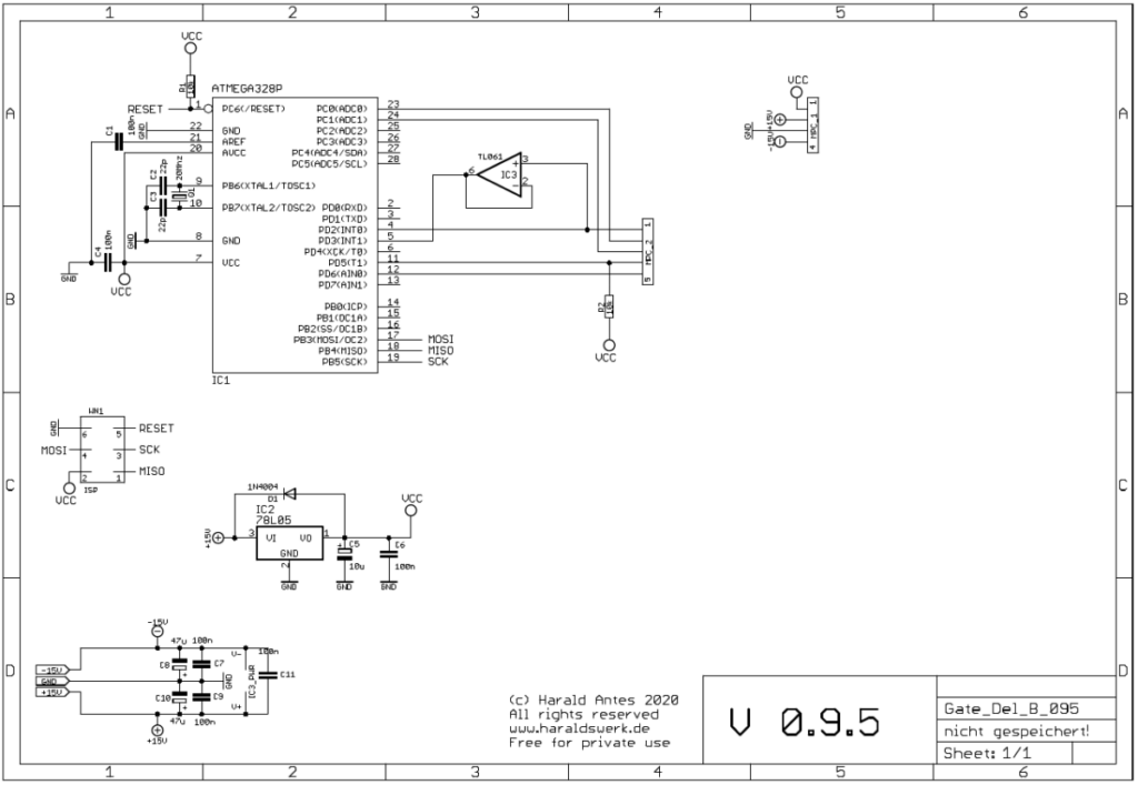
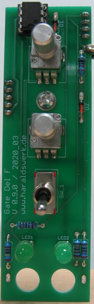
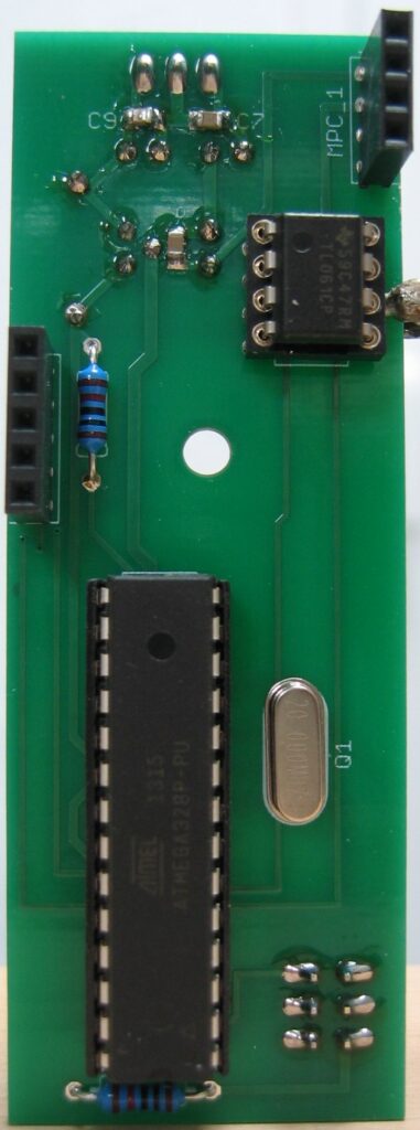
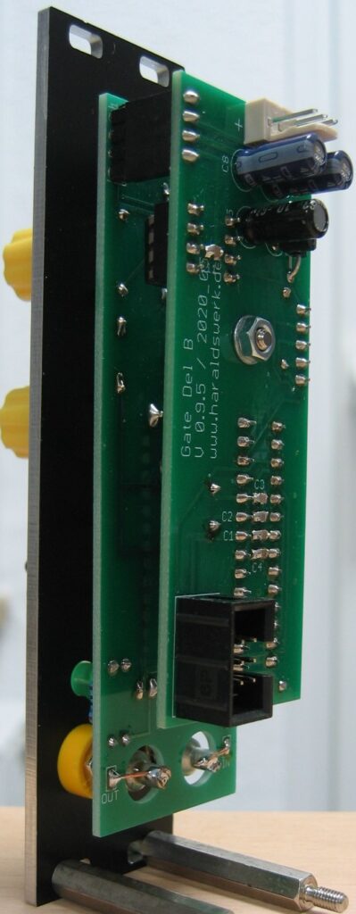
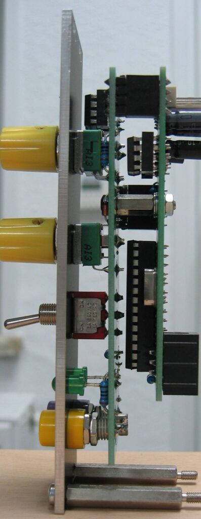
This module starts as a need for my Shakuhachi 2 Synth project. I was in need for a short Gate Delay of about 10ms (which is easy to realize). But then I thought about a more flexible solution with adjustable delay time and optional trimming the gate at the end. To be used elsewhere in the synth as well. So I came up with this solution. The hardware is still simple and the functionality lies in the software. So far I have only realized the function which I need for my Shakuhachi to Synth project. But you can easily improve about this with changing the software.
Specs and features
Gate delay with variable timing
Coarse and fine time adjustment
Gate in and out with LED signaling
End of gate trim
Runs on +/-12V and +/-15V
Power consumption below 30mA positive rail. 5mA negative rail.
The documentation and the Gerber files for download can be found in my website.
Gate delay: Schematic control boardGate delay: Schematic main boardGate delay: Populated control PCBGate delay: Populated main PCBGate delay: Back viewGate delay: Side view
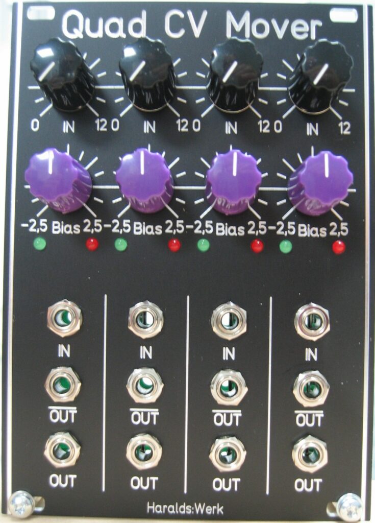
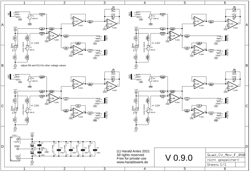
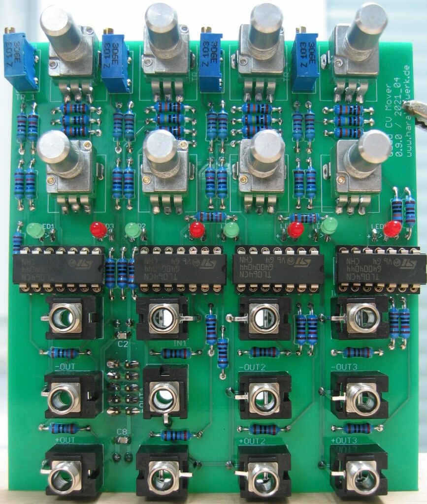
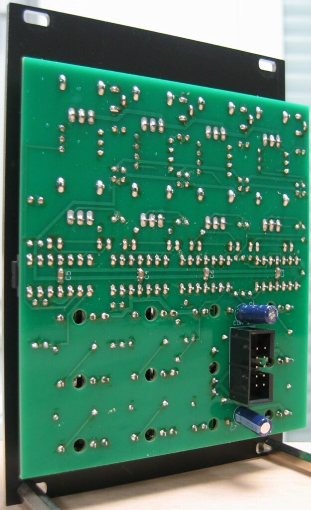
A companion for my other quad modules. Especially for my Quad LFO. You can use it as attenuator, attenuverter, CV Source and, most important, for offsetting bipolar control voltages to make them unipolar, positive or negative. The module is DC coupled, so you can use it for DC and AC. It is possible to offset the input with +/- 2.5V. The offset is signaled with diodes. There is an inverted output added as well. The main usage is for processing bipolar LFO voltages into unipolar control voltage inputs. If you have a LFO with +/- 5V output and want to make it unipolar set the input to halve and the offset to +2.5V. The output is then from 0..5V and 0..-5V at the negative output. You can easily adapt the module to other offset voltages with a few resistor changes.
Specs and features
Attenuator
Inverted and non- inverted output
Attenuverter
+/- 2.5V offset
Runs on +/-12V and +/-15V
Power consumption below 20mA each rail
The documentation and the Gerber files for download can be found in my website.
CV Mover quad: SchematicCV Mover quad: Populated PCBCV Mover quad: Back viewCV Mover quad: Side view
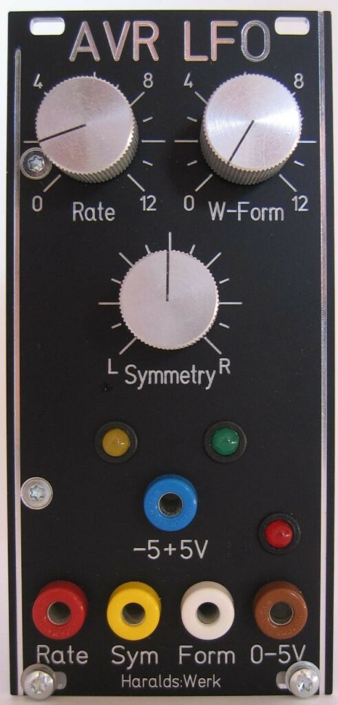
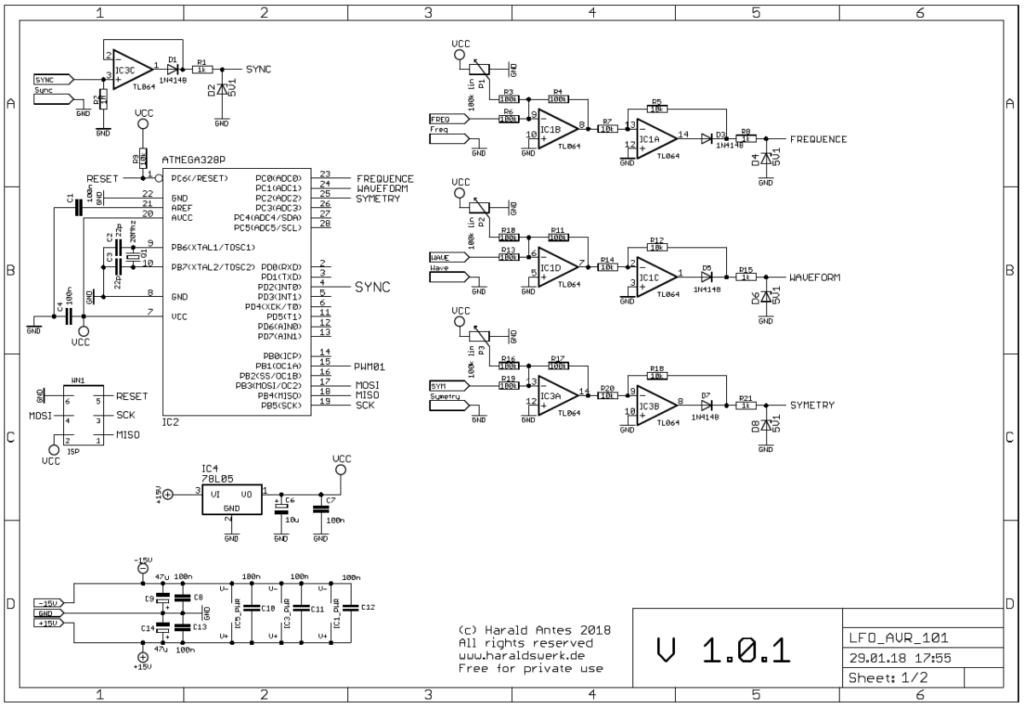
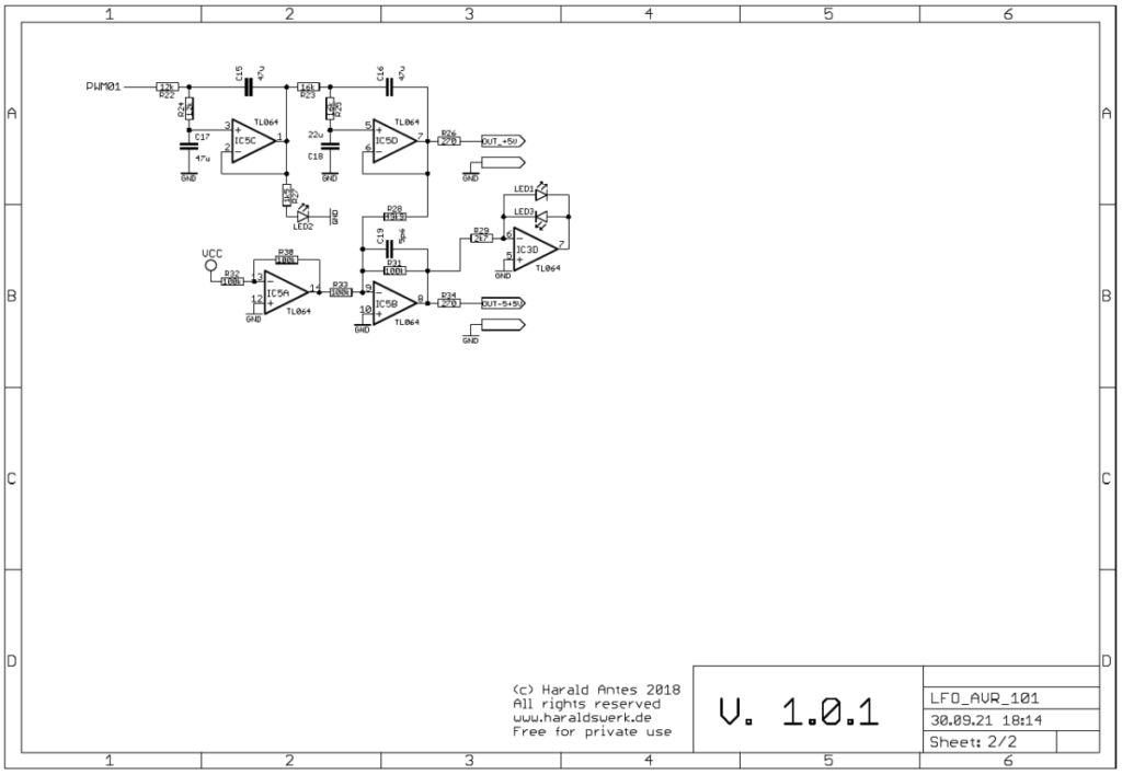
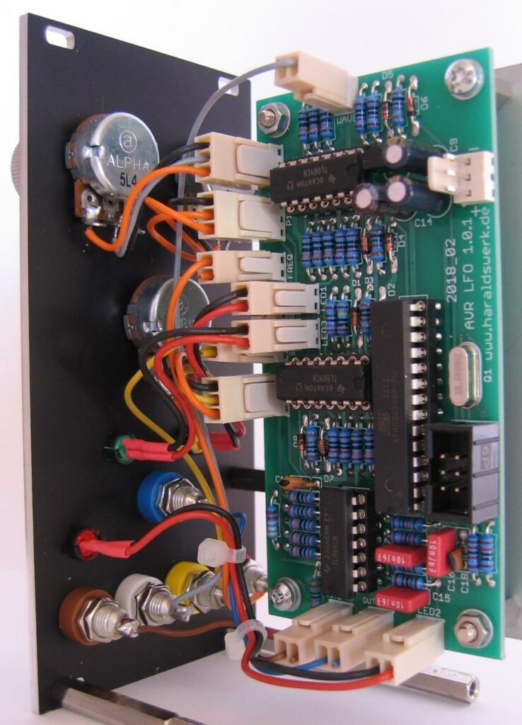
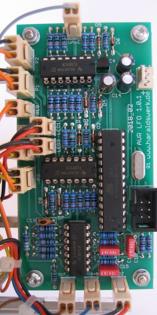
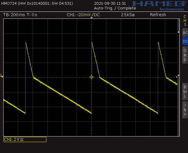
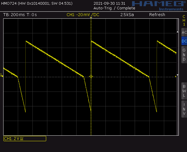
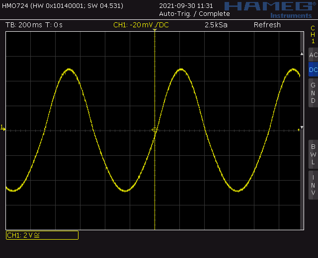
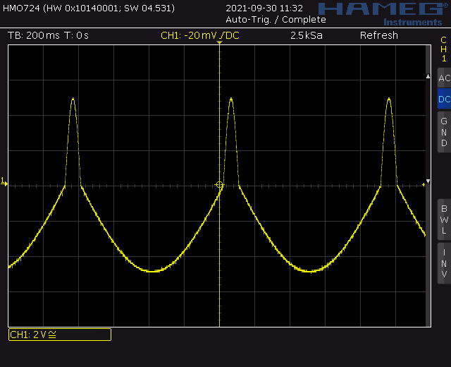
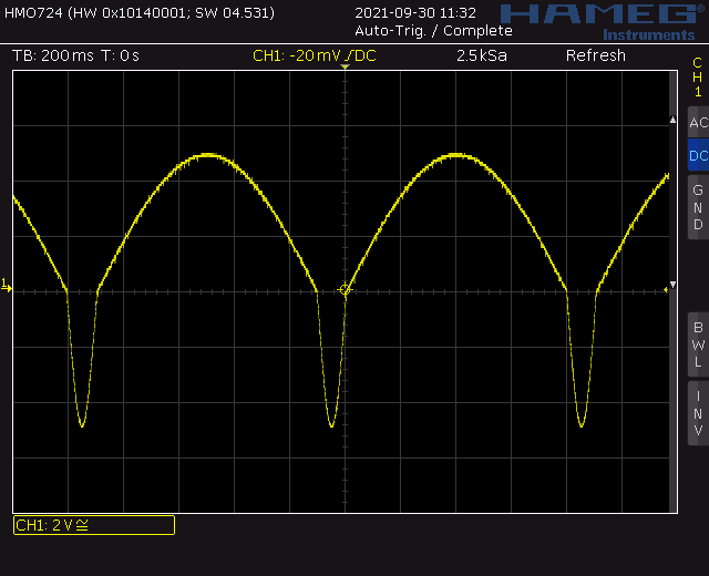
This is an old project dated back to December 2017. It was intended to learn some basics about the hard- and software of the ATMEGA series from AVR. It is kept simple. Just three analog inputs, one interrupt input and PWM output with filter are used. It is up to you what software you want to run on it. Here I made a simple voltage controlled VCO with variable symmetry. Speed, waveform and symmetry are voltage controlled. So you can change the triangle from ramp up to triangle to ramp down. Or make one halve of the sine very small. See screenshots below. This software was mainly written to test the hardware. To my surprise it worked sufficiently well for a LFO. So I leave it as is for the moment. No fancy accumulation with fixed point arithmetic and increment interpolation. Of course there is a lot room for improving the software. I know.
Specs and features
Voltage control for speed, waveform, symmetry
Bipolar and unipolar output
Square, triangle, sine, ramp up, ramp down waveform
20MHz crystal
19.5kHz PWM 10bit resolution
Runs on +/-15V and +/-12V
Power consumption around 30mA positive, 5mA negative rail
The documentation and the Gerber files for download can be found in my website.
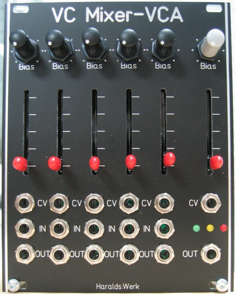
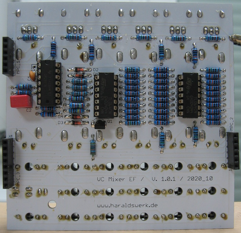
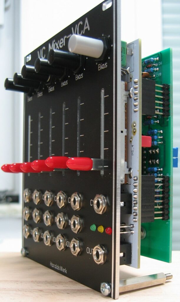
This is basically a combination of 6 VCA configured as a mixer. The five inputs can be used as individual linear VCA or as input channels to the mixer output. All five input channels and the mixer output are voltage controlled. The control voltage inputs for the input channels are normalized so you can modulate all five channels with the same control voltage or group them to your needs. The sliders controls the amount of the modulation per channel. The inputs are normalized as well. This makes for a nice voltage controlled overdrive when used. A level indicator shows the output signal at the summed output. The summed output is voltage controlled as well. Instead of the here used CA3280 (I am using up some NOS) you can use the new available AS3280.
Specs and features
Five voltage controlled inputs
Five independent VCA
Voltage controlled output
Level indicator
Power consumption around 75mA each rail
The documentation and the Gerber files for download can be found in my website.
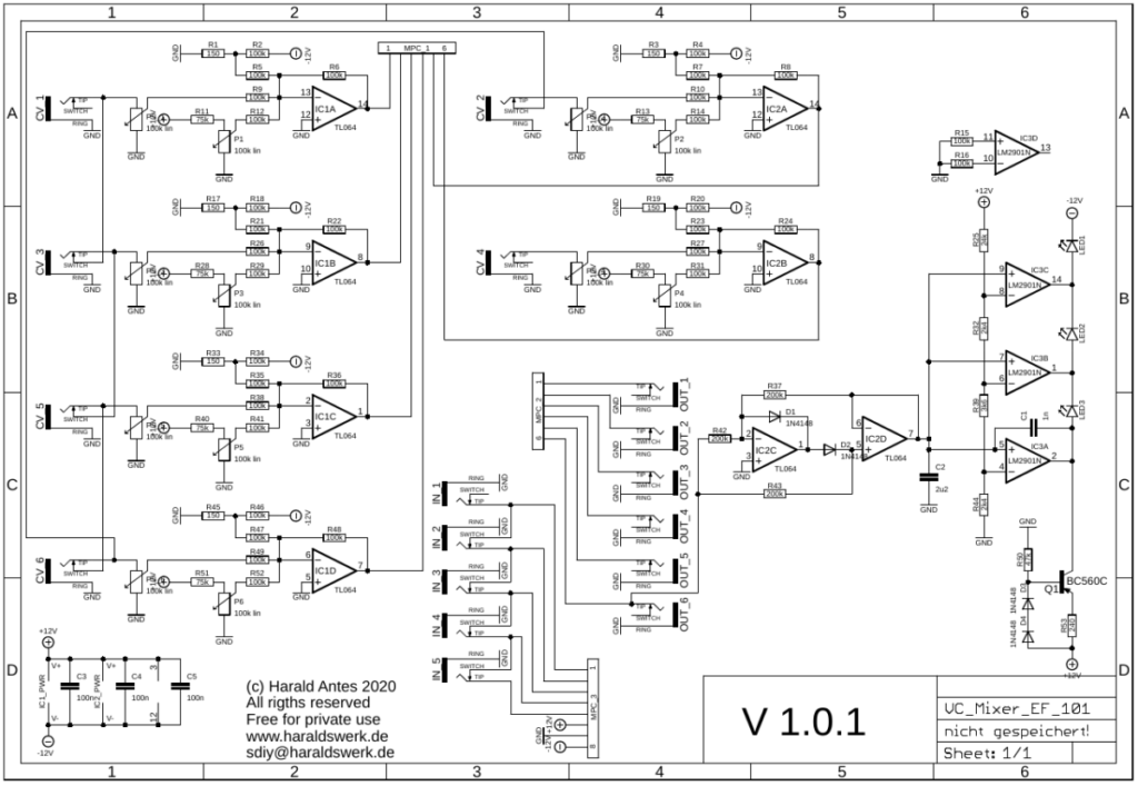
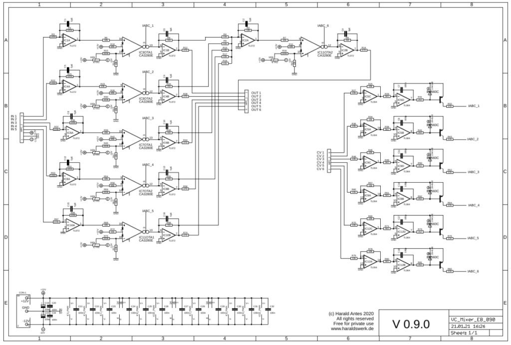
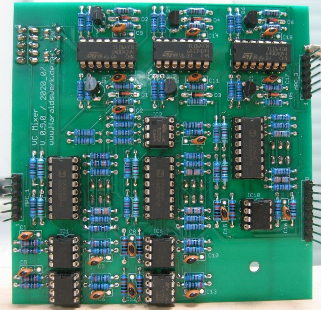
Voltage controlled mixer-VCA: Schematic control boardVoltage controlled mixer-VCA: Schematic main board
On the schematics you can see 6 VCA with linear control current sources. Just as it is done over and over again. Plenty explanations on the web.
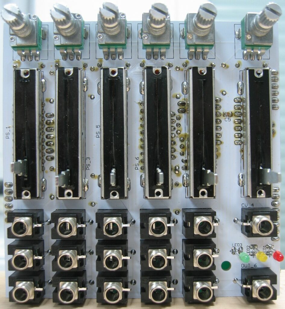
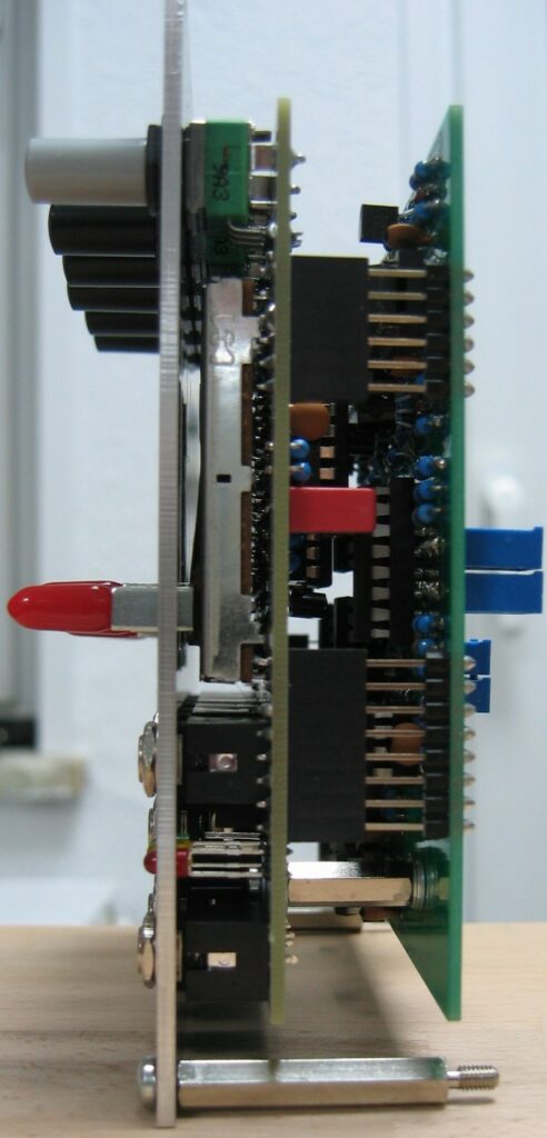
Voltage controlled mixer-VCA: Populated controö board topVoltage controlled mixer-VCA: Populated control board backVoltage controlled mixer-VCA: Populated main boardVoltage controlled mixer-VCA: Side viewVoltage controlled mixer-VCA: Side view
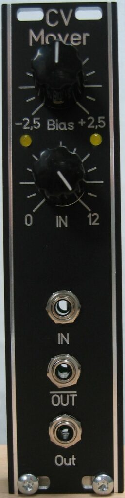
A small but versatile module. You can use it as attenuator, attenuverter, CV Source and, most important, for offsetting bipolar control voltages to make them unipolar, positive or negative. The module is DC coupled, so you can use it for DC and AC. It is possible to offset the input with +/- 2.5V. The offset is signaled with diodes. There is an inverted output added as well. The main usage is for processing bipolar LFO voltages into unipolar control voltage inputs. If you have a LFO with +/- 5V output and want to make it unipolar set the input to halve and the offset to +2.5V. The output is then from 0..5V and 0..-5V at the negative output.
Specs and features
Attenuator
Inverted and non- inverted output
Attenuverter
+/- 2.5V offset
Runs on +/-12V and +/-15V
Power consumption below 10mA each rail
The documentation and the Gerber files for download can be found in my website.
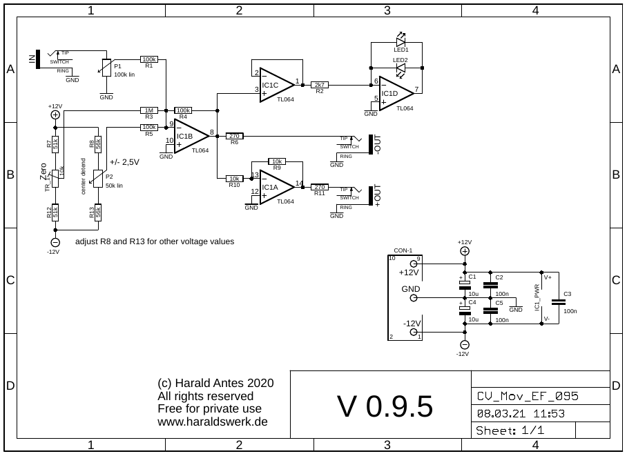
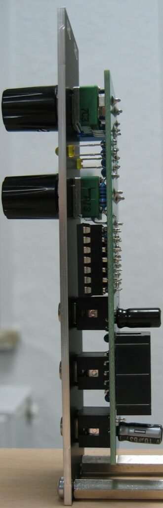
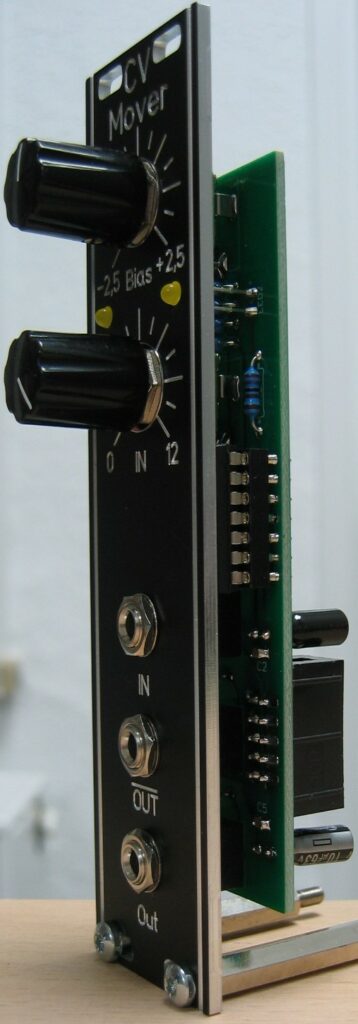
CV Mover: SchematicCV Mover: Populated PCBCV Mover: Side viewCV Mover: Side view
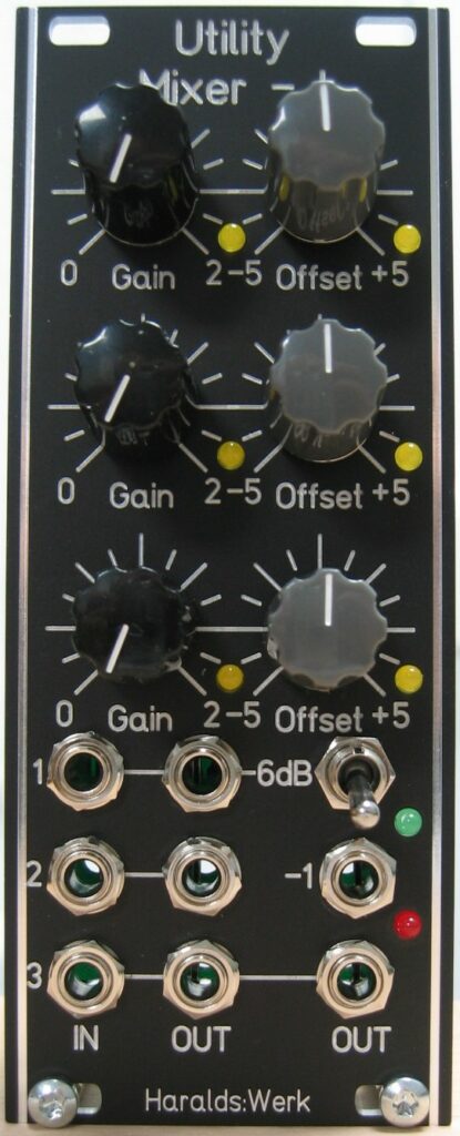
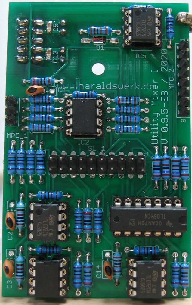
This is an often used utility module. The mixer comes in handy for mixing CV sources. The mixer is DC coupled, so you can use it for DC and AC mixing. The input impedance is constant 1MOhm. The input signals are amplified by a maximum factor of two. It is possible to offset every input with +/- 5V. The offset is signaled with LED’s for every channel and for the summing output. The outputs are normalized, so you can remove selected channels from the output mix. The summed output has a -6dB switchable attenuator. There is an inverted summed output added as well. The added volume indicator us useful for finding the appropriate signal level.
Specs and features
Three inputs, three outputs
Inverted and non- inverted summed output
2x amplification
+/- 5V offset for every channel
-6dB switch
Volume indicator
Normalized outputs
Runs on +/-12V and +/-15V
Power consumption below 20mA each rail
The documentation and the Gerber files for download can be found in my website.
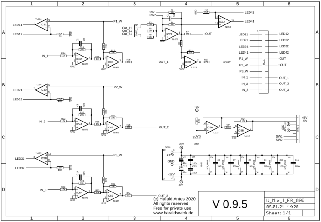
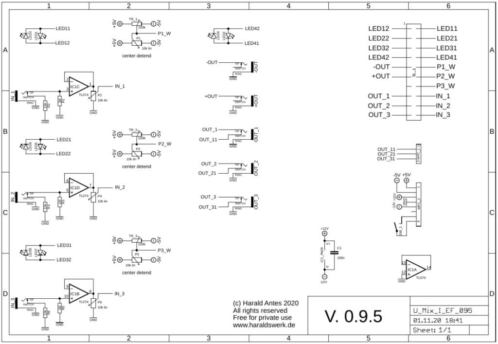
Utility Mixer I: Main boardUtility Mixer I: Control board
Control board: Straight forward design. The mixer is completely DC coupled. So you can use it for CV mixing as well as audio mixing. IC1B,C,D buffers the three inputs and and keeps the input impedance constant. P2, P4, P6 sets the amplification from zero to 2X. P1, P3, P5 sets the offset voltage. The LED indicates the offset and signal level.
Main board: IC3B, IC4B, IC6B adds the offset voltage and the signal. IC1C, IC1D, IC1B, IC1B drive the low current LED. IC2A sums the signals and drives the negative output. IC2B drives the positive output.
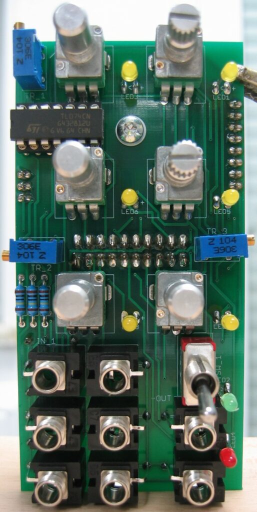
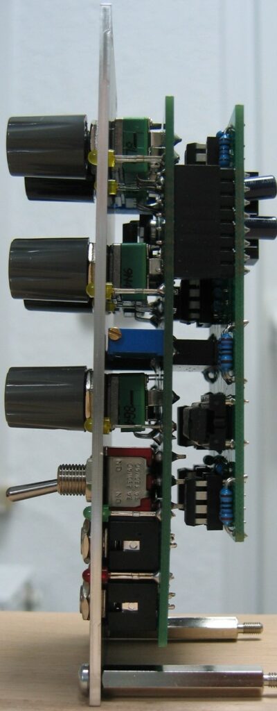
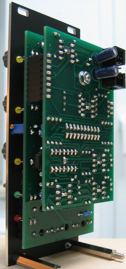
Utility Mixer I: Populated control boardUtility Mixer I: Populated main boardUtility Mixer I: Side viewUtility Mixer I: Back view
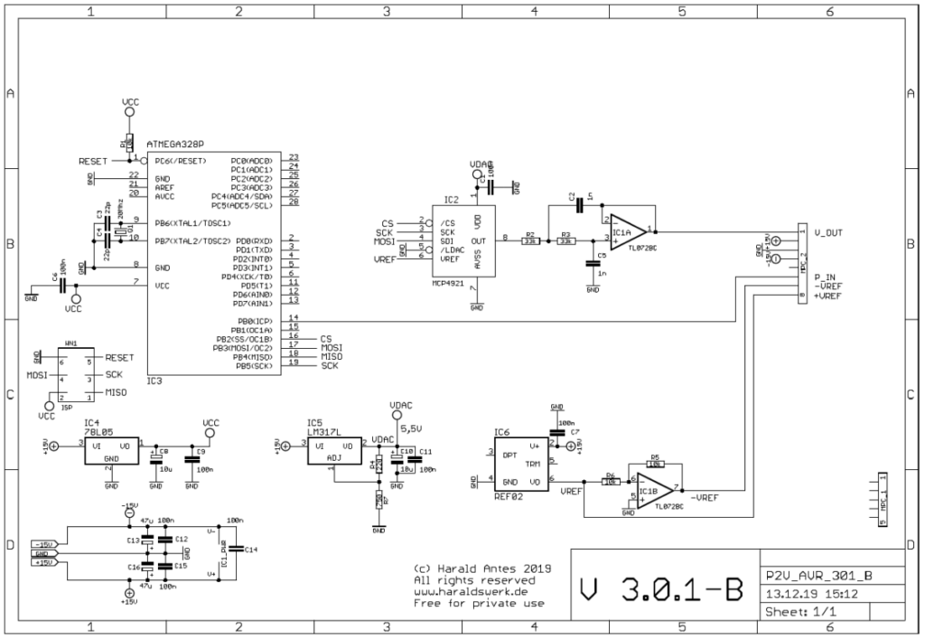
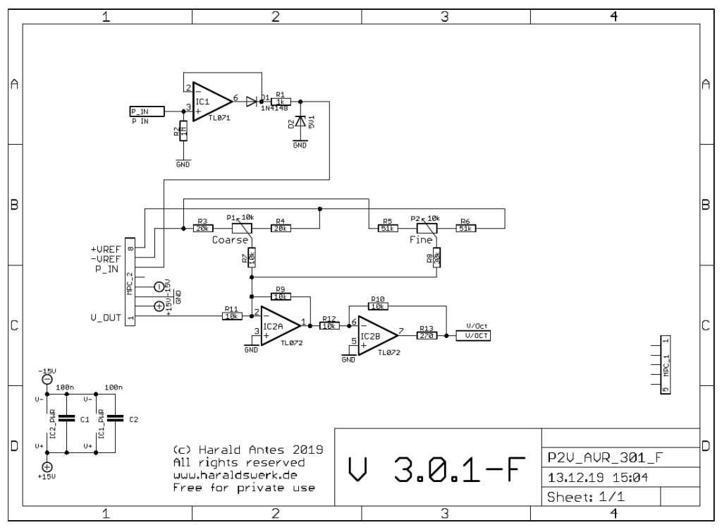
This is the software driven replacement for my all hardware pitch to voltage converter from my Shakuhachi to Synth project. The software driven approach has the advantage of easily adaption for different frequency ranges. In my case it is the range of the Shakuhachi. To change the range just adapt the software. It is completely temperature independent. The needed input is a pulse train derived from your original signal. You can use my Signal to Trigger converter to provide the pulse train. An offset voltage is added to the V/Oct output to fit the needs of your VCO (Synthesizer).
Specs and features
Software driven pitch to voltage converter
12bit resolution
V/Oct output
Offset CV Fine and coarse adjustment
Runs on +/-15V and +/-12V
Power consumption around 45mA positive rail, 15mA negative rail
The documentation and the Gerber files for download can be found in my website.
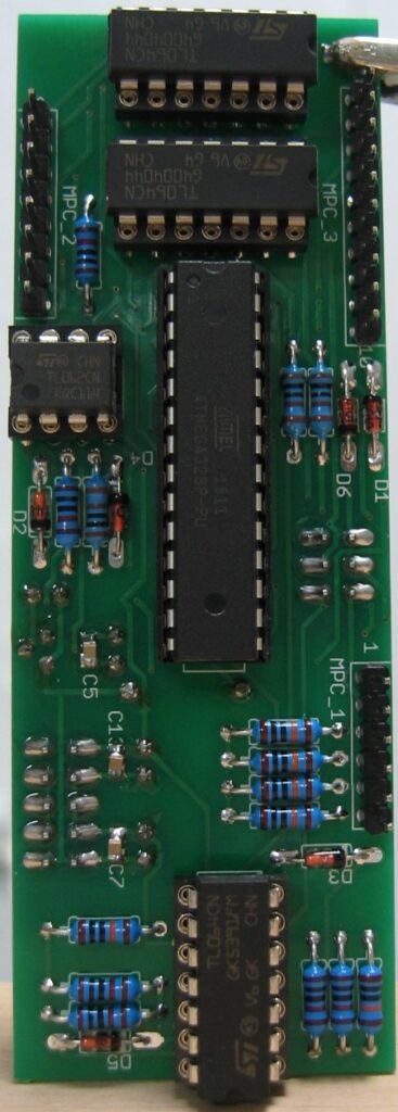
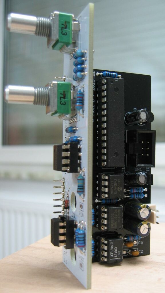
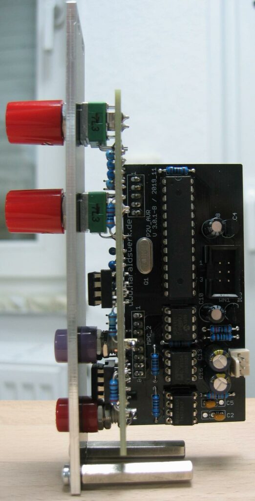
Pitch to voltage converter: Microprocessor boardPitch to voltage converter: Control board
The incoming pulse train is feed to the microprocessor. IC1 (301-F) prevents the microprocessor from negative inputs. Zener D2 prevents from overvoltage. The trigger starts an internal timer of the microprocessor in input capture interrupt mode. The ticks are counted and the count is then looked up in a table. The lookup table provides the values for the V/Oct conversion. The read value is the send to the DAC MCP4921 which is follwed by a low pass (IC1A, 301-B)). IC2A (301-F) adds the offset voltage and IC2B (301-F) corrects the phase.
Pitch to Voltage converter: Populated PCB’sPitch to Voltage converter: Side view